
Operating instructions


4
1. INTRODUCTION:
The 3100 Smart Pressure Transmitter is calibrated at the factory
before shipping. To ensure correct and efficient use of the instru-
ment, please read the manual thoroughly and fully understand
how to operate the instrument before operation.
The contents of this manual are subject to change without prior
notice.
All rights are reserved. No part of this manual may be reproduced
in any form without the written permission of Taco, Inc.
If any question arises, errors are found or if any information is
missing from this manual, please inform Taco, Inc.
The specifications covered by this manual are limited to standard
transmitters and do not cover custom-made instruments.
Please note that changes in the specifications, construction, or
component parts of the instrument may not immediately be
reflected in this manual at the time of change, provided that post-
ponement of revisions will not cause difficulty to the user from a
functional or performance standpoint.
1.1 Using This Manual:
The operating manual provides information on installing, operat-
ing, and maintaining the Taco Model 3100 Smart Pressure
Transmitter. The sections are organized as follows:
Section 2 – Handling Cautions
Section 2 provides instructions on commissioning and operat-
ing the Model 3100 Smart Pressure Transmitters. Informations
on software functions, configuration parameters, and on-line
variables are also included.
Section 3 – Transmitter Functions
Section 3 contains suggestions on handling the Model 3100
Smart Pressure Transmitter.
Section 4 – Installation
Section 4 contains mechanical, environment consideration and
electrical installation instructions for the Model 3100 Smart
Pressure Transmitter.
Section 5 – On-line Operation
Section 5 describes how to configure the parameters of the
Model 3100 Smart Pressure Transmitter. See the following list
for the details.
1. Regulations for circuit's Input/Output characteristics; Sensor
or Output Trim
2. Changing the output characteristic; Range Configuration,
Output Type, Dampening, Unit
3. Changing the general data; Tag No., Date, Message etc.
Section 6 – Maintenance
Section 6 contains hardware diagnostics, troubleshooting and
maintenance tasks.
1.2 Overview of Transmitter:
The Taco Smart Pressure Transmitter is a microprocessor based
pressure transmitter with a capacitance sensor optimized for draft
measurement. The Model 3100 has a true draft analog range from
0 to 20 mA. This transmitter is explosion-proof, high precision
accuracy, reliability and has digital communication for remote
communication system.
The Model 3100 is enabled with HART
®
communication with Host,
HHT (HART
®
Communicator) or PC Configurator. The transmitter’s
various variables in host are able to be changed, configured and
calibrated by users. The HART
®
Communication between DC
power supply and transmitter requires a 250 - 550 Ohm resistance.
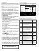
1.3 Software Compatibility:
The Taco Smart Pressure Transmitter's software is implemented
at the factory. The following functions can be configured using a
HHT (Hart
®
Communicator).
• – Supported ∆ – Supported but update required
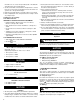
2. HANDLING CAUTIONS:
This section consists of cautions for transmitter handling, storage,
installation, insulation and explosion structure, etc.
HART
®
is a registered Trademark of Hart
Communication Foundation.
FUNCTION
FUNCTION SUPPORTS
ZERO/SPAN
Button
PC/PDA
HART
HHT
Rev. 58
ZERO/SPAN
•
• •
ZERO/TRIM
•
• •
ZERO Adj
•
• •
Units set
•
• •
Range set
•
• •
Dampening set
•
• •
LCD decimal set
•
•
∆
JOB JOB DETAILS INSTRUMENT
U
npacking
•
Unpack transmitter packing.
Model and
Specifications
• Make sure the transmitter nameplate
matches the model number on the P.O.
Storage
• In a dry, non-vibration and non-impact
area.
• Ambient temperature around 77°F (25°C)
and 65% relative humidity.
Calibration
• Configuration of the Range, Zero/Span,
Unit, Tag, Dampening Time, Transfer
Function, DA Trim and other parameters.
HHT
Pressure Source
Galvanometer
Installation
Locations
• Where ambient temperature is constant.
• Exposure to chemical corrosion, etc.
• Where shock and vibration are minimal.
• Where the area classification does not
exceed the explosion-proof rating.
• Where maintenance is easy.
(Engineering)
Mechanical
Considerations
• Where the transmitter can be handled easily.
• Be cautious of process connections leaking.
(Engineering)
Electrical
Considerations
• 24 VDC
(Power Supply is 11.9 VDC - 45 VDC).
• For HART
®
communication, resistance on
transmitter terminal loop should be
between 250 -550 ohms.
(Engineering)
Mounting and
Installation
• When mounting the transmitter, an appro-
priate bracket should be used.
• The transmitter should be mounted securely
to prevent swing.
(Mounting and
Installation)
Calibration on
Spot
• Sensor Zero Trim should be done ten sec-
onds after differential pressure stabilizes.
• Make sure that PV value is zero and
current is 4 mA.
HHT or
Zero/Span
Button
Pressure
• Do not apply a regulated differential pres-
sure and line pressure.
• Close the equalizing valve on the 3 valve
manifold and then open the valve on high
and low side slowly and simultaneously.
(Applying
Pressure)
Operation • Make sure the instrument operates properly. Eye or HHT