
Operating instructions


5
2.1 Unpacking Transmitters:
When moving the transmitter to the installation site, keep it in the
original packaging. Unpack the transmitter at the installation site
to avoid damage on the way.
2.2 Model and Specifications Check:
The model number and specifications are indicated on the name-
plate. Please check the specification and model number.
2.3 Storage:
The following precautions must be observed when storing the
instrument, especially for a long period of time.
1. Select a storage area that meets the following conditions:
- is not exposed to rain or water
- minimal vibration and shock
- stored at normal temperature and humidity
(approx. 77°F (25°C), 65% RH)
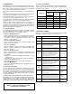
The ambient temperature and relative humidity ratings are:
- Ambient Temperature:
-40 to 185°F (-40 to 85°C) (without LCD module)
-22 to 176°F (-30 to 80°C) (with LCD module)
- General Use: -4 to 140°F (-20 to 60°C)
- Relative Humidity: 5% - 98% RH at 104°F (40°C)
2. When storing the transmitter, repack it the way it was delivered
from the factory.
3. If storing a used transmitter, thoroughly clean the diaphragm
surfaces, so that no media remains. Make sure the transmitter
assemblies are securely mounted before storing.
2.4 Selecting Installation Locations:
The transmitter is designed to withstand severe environmental
conditions. However, to ensure stable and accurate operation, the
following precautions must be observed when selecting an instal-
lation location.
1. Ambient Temperature
Avoid locations subject to wide temperature variations or a sig-
nificant temperature gradient. If the location is exposed to radi-
ant heat from plant equipment, provide adequate insulation or
ventilation.
2. Ambient Atmosphere
Avoid installing the transmitter in a corrosive atmosphere. If the
transmitter must be installed in a corrosive atmosphere, there
must be adequate ventilation. Precautions must be put into
place to prevent intrusion or stagnation of rainwater in conduits.
3. Shock and Vibration
Select an installation site with minimum shock and vibration
(although the transmitter is designed to be relatively resistant to
shock and vibration).
4. Installation of Explosion-Proof Transmitters
Explosion-Proof transmitters can be installed in hazardous
areas according to the gas types for which they are certified.
5. Select a place where the transmitter can be maintained easily.
2.5 Calibration after Installation:
Sensor Zero Trim should be done after transmitter is installed,
because the zero point is not configured for mounting status.
When calibrating the Sensor Zero Trim apply a pressure for zero
in advance, Sensor Zero Trim the sensor when the pressure is suf-
ficiently stabilized (after approximately 10 seconds).
There are two ways to pressure zero. One way is to apply zero dif-
ferential pressure (making pressure the same on both the high and
low side). The other is to close High and Low side of a 3 valve
manifold and open the equalizing valve.
Sensor Zero Trimming can also be done with the Zero/Span but-
ton or a HHT (HART
®
Communicator), PC or PDA configurator.
Refer to On-line Operation for configuring other parameters.
2.6 Pressure Connections:
The following precautions must be observed in order to safely
operate the transmitter under pressure.
1. Never apply a pressure higher than the specified maximum
working pressure.
2. Confirm the option pressure of transmitter. It is necessary to
use standardized and quality-approved parts.
3. There should be isolation valves in case of leakage.
2.7 Waterproofing Cable Conduit Connections:
Apply a non-hardening sealant (silicone or tape, etc.) to the
threads to waterproof the transmitter cable conduit connections.
2.8 Restrictions on Use of Radio Transceivers:
2.9 Installation Resistance Test and Dielectric Strength Test:
Since the transmitter has undergone insulation resistance and
dielectric strength tests at the factory, normally these tests are not
required. However, if required, observe the following precautions
in the test procedures.
1. Do not perform such tests more frequently than necessary. Even
test voltages, that do not cause visible damage to the insulation,
may degrade the insulation and reduce safety margins.
2. Never apply a voltage exceeding 500VDC for the insulation
resistance test, or a voltage exceeding 500VAC for the dielec-
tric strength test.
3. Before conducting these tests, disconnect all signal lines from
the transmitter terminals. Perform the tests in the following pro-
cedures.
2.9.1 Insulation Resistance test:
1. Short-circuit the + and - SUPPLY terminals in the terminal box.
2. Turn OFF the insulation tester. Then connect the insulation
tester plus (+) lead-wire to the shorted SUPPLY terminals and
the minus (-) lead wire to the grounding terminal.
3. Turn ON the insulation tester power and measure the insulation
resistance. The voltage should be applied briefly to verify that
insulation resistance is at least 20MΩ.
4. After completing the test and being very careful not to touch
exposed conductors, disconnect the insulation tester and con-
nect a 100kW resistor between the grounding terminal and the
short-circuiting SUPPLY terminals. Leave this resistor connect-
ed at least three seconds to discharge any static potential. Do
not touch the terminal while it is discharging.
2.9.2 Dielectric Strength Test:
1. Short-circuit the + and - SUPPLY terminals in the terminal box.
2. Turn off the dielectric strength tester. Then connect the tester
between the shorted SUPPLY terminal and the grounding ter-
CAUTION: Instrument installed in the process
under pressure. Never loosen or tighten as it may
cause dangerous spouting of process fluid. If the
process fluid is toxic or otherwise harmful, take
appropriate care to avoid contact or inhalation of
vapors even after disconnecting the instrument
from process line for maintenance.
WARNING: Although the transmitter has been
designed to resist high frequency electrical noise,
if a radio transceiver is used near the transmitters
external wiring, the transmitter may be affected by
high frequency noise pickup. To test for such
effects, bring the transceiver in slowly from a dis-
tance of several feet from the transmitter, and
observe the measurement loop for noise effects.
Always use the transceiver outside the area affect-
ed by noise.