
User's Manual


Sensor Maestros
P a g e | 12 Revised: Novermber 30, 2022
3. PCB Antenna Bandwidth
One way of measuring the bandwidth after the antenna is implemented on a PCB and connected to a transmitter is
to write test software that steps a carrier across the frequency band of interest. By using the maximum hold function
on a spectrum analyzer, the variation in output power across frequency can easily be measured.
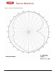
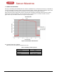
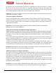
Figure 9 shows how the output power varies on the IFA when the PCB is horizontally oriented and the receiving
antenna has horizontal polarization. This measurement was not performed in an anechoic chamber, thus the
graph shows only the relative variation for the given frequency band.
Figure 9. Bandwidth of PCB Antenna
4. Conclusion PCB Trace Antenna
Table 2 lists the most important properties for the IFA.
Table 2. Summary of IFA
Properties
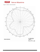
Gain in XY plane
1.1
dBi
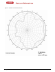
Gain in XZ plane
3.3
dBi
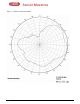
Gain in YZ plane
1.6
dBi
Reflection
< –15
dB
Antenna size
25.7 × 7.5 mm