
User's Manual
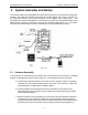
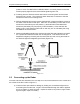

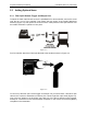
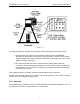
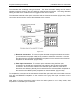


Table Of Contents

pulseEKKO PRO TLF Transmitter 2-System Assembly and Startup
7
Figure: 2-5
The steps necessary to complete the connection of the remote trigger and beeper unit are:
1) The black fiber optic cable of the dual cable connects from the red REMOTE
receptacle on the console to the OUTPUT (grey) fiber optic connector on the remote
trigger and beeper unit. This connection is necessary for the trigger part of the remote
trigger and beeper unit to work.
2) The short single fiber optic cable connects from the INPUT (black) fiber optic
connector on the remote trigger and beeper unit to the OUTPUT (grey) receptacle on
the transmitter. This connection is necessary for the beeper part of the remote trigger
and beeper unit to work.
During data acquisition, the beeper will emit a beep as data are being collected.
As well, when the radar system is run in Step mode, data acquisition can be controlled using the
button on the remote trigger and beeper unit.
2.3.2 Odometer
The pulseEKKO Pro odometer is useful for collecting data at a user defined stepsize (1 cm to 10
m) without the necessity of a tape measure or survey makers.