
User's Manual
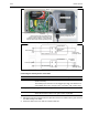
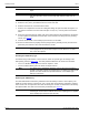


Table Of Contents

Rev A WGS Configuration
FlexZone Wireless Gate Sensor Page 15
method to simulate a climb intrusion is to actually climb on the fence fabric (you do not have to
climb over the fence). Begin the tests on the protected surface at the farthest point away from the
GSM. The UCM GSM Status window displays information about the gate sensor modules. Use the
UCM Magnitude Response Plot to calibrate and monitor the gate sensor module’s response.
1. Connect the UCM to the FlexZone processor.
2. Select the GM Status tab.
3. With the gate in its closed secure position, select the reset button. (The reset button sets the
current position of the GSM as the secure position.)
4. Verify the status of the GSM (no faults or alarms).
5. Select the Magnitude Response Plot button to open a plot window (see Figure 16:
).
Figure 15 GSM status window
GSM Status tab
GSM firmware version
diagnostic status indicators
green = OK, purple = fault, gray = no fault,
question mark = status unknown
communication power indicator (bar graph)
Red indicate GSM Alarm active
Event Count and Event Magnitude
for current activity
select to open a Magnitude Response Plot
purple indicates GSM supervision condition
select Reset to set the current position of
the GSM as the secure operating position
current status of auxiliary input
current power level (capacity)
current power source (Main)
temperature readings (current, max., min.)