Transmitter Certification Test Report FCC ID: SDBFPGMR FCC Rule Part: CFR 47 Part 15.209 ACS Report Number: 07-0270 – 15C Applicant: Sensus Metering Systems Model(s): FPGMR User’s Guide 5015 B.U.
450 N. Gallatin Avenue Uniontown, PA 15401 FLEXNET Field Programmer (FPGMR) INSTALLATION TOOL USER’S GUIDE Draft Copy 8-24-06 VO.
Table of Contents 1 FPGMR Power Button…………………………………….3 2 GPS LINK OK………………………………………..4 3 Installation Process…………………………………….7 4 Appendix A: Regulatory Information………………….
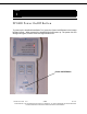
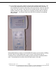
Section 1 FPGMR Power On/Off Button To power up the Handheld Installation Tool, press the Power On/Off button in the bottom left hand corner. When pressed, the Handheld Unit will power up. The power OK LED will light solid green, and the GPS LINK light will blink red. Power On/Off Button FPGMR User’s Guide VO.1 3 OF 8 03-17-06 TO BE USED ONLY FOR THE PURPOSE FOR WHICH IT IS SUBMITTED. ALL RIGHTS RESERVED TO SENSUS METERING SYSTEMS. REPRODUCTION WITHOUT WRITTEN CONSENT IS PROHIBITED.
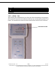
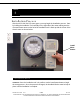
Section 2 GPS LINK OK After Powering the Handheld device, the GPS LINK LED will be blinking red meaning the GPS receiver in the unit has not achieved a GPS lock yet, and the current position is not known. The Handheld unit cannot be used to install a meter until GPS lock is achieved. GPS LINK OK LED FPGMR User’s Guide VO.1 4 OF 8 03-17-06 TO BE USED ONLY FOR THE PURPOSE FOR WHICH IT IS SUBMITTED. ALL RIGHTS RESERVED TO SENSUS METERING SYSTEMS. REPRODUCTION WITHOUT WRITTEN CONSENT IS PROHIBITED.
2.1 In an outdoor open space, hold the unit with LEDs pointing towards the sky. The unit can also be placed face up on any flat surface until GPS lock is achieved. If the handheld unit is turned on after being off for several hours, GPS lock may take longer, up to four minutes. After that, the unit should only take a few seconds to acquire a GPS lock. When a GPS lock is acquired, the GPS LINK OK LED will light solid green. A solid green light means that GPS coordinates are updating every second.
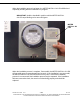
Section 3 Installation Process After the GPS LINK OK LED turns green, you may begin the installation process. Start by holding the Installation Tool vertically on the right side of the meter making sure the command meter arrow on the left of the Installation tool is lined up with the center of the electric meter as shown below. Install Meter Button 3.1 Installation Button Installation: Once the installation tool is in position, use the install meter button to begin the setup process.
When the Installation process has begun, the METER INSTALL OK LED will blink red repeatedly showing that the installation is in progress. *IMPORTANT* Hold the handheld in position until the METER INSTALL OK LED stops blinking red or turns solid green. METER INSTALL OK LED When the installation process is complete, if successful, the METER INSTALL OK LED will turn solid green for approximately four seconds. If the installation is not successful, the METER INSTALL OK LED will not be lit in any color.
APPENDIX A: REGULATORY INFORMATION: COMPLIANCE INFORMATION: FCC: NOTE: This equipment has been tested and found to comply with the limits for a Class B digital device, pursuant to Part 15 of the FCC rules. These limits are designed to provide reasonable protection against harmful interference in a residential installation.