Transmitter Certification Test Report FCC ID: SDBTGB001LP/SDBTGB001HP FCC Rule Part: CFR 47 Part 24 Subpart D, Part 90 Subpart I, Part 101 Subpart C ACS Report Number: 05-0169-LP/05-0169-HP Manufacturer: Advanced Metering Data Systems, LLC Equipment Type: Base Station Transceiver Model(s): TGB001LP TGB001HP Users Manual 5015 B.U.
TGB 900MHz Users Manual & Operators Guide Prepared by: AMDS 2021 Lakeshore Dr. Suite 414 New Orleans, LA 70122 PH: (504)304-2502 1 To be used only for the purpose for which it is submitted. All rights reserved to AMDS LLC. Reproduction without written consent is prohibited.
1. DESCRIPTION 1.1. Purpose The purpose of this document is to provide necessary information for use by field personnel in the installation, operation, and troubleshooting of the 900MHz Cell Tower Gateway Basestation (TGB). 2 To be used only for the purpose for which it is submitted. All rights reserved to AMDS LLC. Reproduction without written consent is prohibited.
1.2. FCC Class B Statement “NOTE: This equipment has been tested and found to comply with the limits for a Class B digital device, pursuant to Part 15 of the FCC Rules. These limits are designed to provide reasonable protection against harmful interference in a residential installation. This equipment generates, uses, and can radiate radio frequency energy and, if not installed and used in accordance with the instructions, may cause harmful interference to radio communications.
1.3. Industry Canada This Class B digital apparatus meets all requirements of the Canadian Interference Causing Equipment Regulations. Operation is subject to the following two conditions: (1) this device may not cause harmful interference, and (2) this device must accept any interference received, including interference that may cause undesired operation. Cet appareillage numérique de la classe B répond à toutes les exigences de l'interférence canadienne causant des règlements d'équipement.
1.4.3 General Information The TGB Transceiver is a high performance burst data radio system. The RF receiver is configured to receive 3 distinct modulation schemes on 3 adjacent frequencies in the 896 to 940 MHz frequency range. The TGB RF Transmitter operates on a single configurable channel (12.5kHz, 13.6 KHz, or 25kHz authorized bandwidth depending on the channel and FCC Rule section governing it’s operation) in the 935 to 960 MHz frequency range.
1.5. Block Diagram 1.5.1. Power System !!! Danger !!! Hazardous AC voltages capable of producing severe electrical shock are present at various locations in the TGB. Exercise caution when working inside the enclosure, to assure that contact is not made with and electrical termination. !!! Warning !!! The batteries are a source of energy and can be hazardous if shorted. Exercise caution. 1.5.1.1.
1.5.2. Wiring The TGB equipment enclosure wiring is supplied in another document and is beyond the scope of this manual. All TGB connections to the wiring and interconnect of the TGB equipment enclosure are provided below to assist the operator in installing the TGB inside the equipment enclosure. 1.5.3. Alarms 1.5.3.1. Intrusion The enclosure the TGB is mounted in is equipped with pin switches on both the front and rear doors that activate and intrusion alarm when a door is opened.
nor should any adjustments be made to the tuning screws of the Cavity Filter / Duplexer by the operator. 1.5.4.3. RF Cabling The RF cabling and connectors inside the TGB enclosure are selected due to their low-loss characteristics. No cables or connectors should be changed or replaced by the operator. 1.5.5. Breakout Panel Assembly The purpose of the Breakout Panel is to function as an interface between the Fusion Processor and the “external world”.
2.2.2. Power/Battery !!! Warning !!! Do not make any connections with power applied to the system. The batteries are a source of energy and can be hazardous if shorted. Exercise caution. Prior to connecting batteries, disconnect the battery cable from the right hand side of the rectifier cabinet. Install batteries and connect jumpers to battery terminals. Before reconnecting battery cable to right hand side of rectifier cabinet, measure open circuit voltage between pins 1 & 2.
Antenna Co-Location At Multiple-Transmitter Sites: According to § 1.1307(b)(3), the FCC requires the following (excerpted from CFR 47): (3) In general, when the guidelines specified in § 1.
IF ANY RED LIGHTS ARE DISPLAYED ON THE TGB FRONT PANEL, POWER DOWN THE UNIT AND CALL THE OPERATIONS CENTER FOR FURTHER INSTRUCTIONS. 3. Operation 3.1. General The TGB is designed to operate with minimal user intervention—even in the event of commercial AC power interruption. Specialized software may be used (available ONLY to authorized AMDS technical personnel pursuant to the requirements of CFR 47 Part 90.
the FCC Rules. Highly controlled and specialized software, protected using password login is utilized (either through a specialized diagnostic port or via a secure internet link to the TGB) by ONLY AMDS authorized personnel, to program any of the on-air operational parameters of the TGB. 3.2. Starting and Stopping Prior to powering down the TGB Electronics, the Halt command should be issued to the Fusion Processor via the internet link or by qualified AMDS service personnel.
3.3.
The system provides for local visual (BATTERY FAILURE) and remote indication the system output voltage has fallen below a preset level. This level is set at the factory at 24V. The alarm clears automatically when the system output voltage increases above this level. The Low Voltage Alarm is the final indication that the TGB system is about to shut down. Once asserted the TGB will shutdown in approximately 8 hours unless commercial AC power is restored.. 4. Maintenance 4.1.
4.4. Battery Replacement !!! Warning !!! The batteries are a source of energy and can be hazardous if shorted. Exercise caution. The batteries are rated for a 5-yr life at 25˚C and 27.5VDC float voltage. Extended periods of operation above 25˚C will reduce battery life (rule of thumb: 50% life reduction per every 10˚C increase. After this time it is appropriate to have a change-out program. In the event of frequent deep discharges it is possible that the batteries may require earlier replacement.
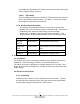
5. Ordering Information and Parts List 5.1. Spares Kit Description Antenna Surge Arrestor Gas Tube Generator Plug 1 1/3A GMT Fuse 2A GMT Fuse 5A GMT Fuse Manufacturer Andrews Andrews Hubbell Bussmann Littlefuse Bussmann Littlefuse Bussmann Littlefuse Part Number APG-BNFNF-090 GASTUBE-090 2713 GMT - 1 1/3 A HB481001.33 GMT - 2 A HB481002 GMT - 5 A H481005 16 To be used only for the purpose for which it is submitted. All rights reserved to AMDS LLC. Reproduction without written consent is prohibited.