
Installation Guide
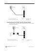
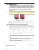
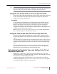

Table Of Contents
- Sensys Networks VDS240 Wireless Vehicle Detection System
- Access Point Controller Card (APCC) Installation Guide
- Contents
- Introduction
- Overview
- Access Point Controller Card (APCC)
- Types of APCC Configurations
- APCC Package Contents
- SPP Package Contents
- Additional Parts and Equipment Required
- 1. Cabling – a minimum of one straight-through Ethernet cables are required.
- 2. Laptop PC and TrafficDOT software – if contact closure cards will be configured via TrafficDOT's GUI, a suitable host is required.
- 3. Contact closure card functions can be configured from the switches on the front panel eliminating the need for a laptop PC and TrafficDOT.
- APCC Installation Considerations
- SPP Installation Considerations
- APCC Installation Procedures
- SPP Installation Procedures
- Tools Required for SPP Installation
- Step-by-Step Procedures
- Installing the Mounting Plate on Poles
- Installing the Mounting Plate on Walls
- Installing the Mounting Plate on Beams
- Determining the Type of SPP Radio Bulkhead Connector
- Connecting the Cable to an SPP Radio with the Hex-head Connector
- Step-by-Step Procedures
- Figure 6.6. Remove the factory-installed cap
- Figure 6.7. Inspect the factory-installed gasket
- Figure 6.8. Replace damaged or used gaskets
- Figure 6.9. Thread cable through connector A
- Figure 6.10. Thread cable through connector B
- Figure 6.11. Ethernet cable bushing chart (not to scale)
- Figure 6.12. Fit bushing onto cable between connector A and connector B
- Proper Fit (little to no gap between edges of cut)
- Improper Fit (gap between edges of cut)
- Proper Fit (bushing fully seated into guides)
- Improper Fit (bushing poorly seated into guides)
- Proper Fit (recessed bushing, smooth face)
- Improper Fit (bushing not recessed, pinched edge, mushroomed face)
- Removing the Cable Connection
- Configuration
- Overview
- Configuring Channels With the Front-Panel Interface
- Starting TrafficDOT and Connecting to an APCC
- Configuring Channels with TrafficDOT
- Defining Sensor-to-Channel Mappings
- Exiting TrafficDOT
- X Mode LED Displays for Slot Numbers
- Circuit-board Dip Switch SW1 Settings
- Circuit-board Dip Switch SW2 Settings
- Pre-Installation Worksheets
- Contact Closure Card External Interfaces

SPP Installation Considerations
Access Points Controller Card (APCC) 15
Sensys Networks, Inc. Installation Guide
Voltages
The APCC uses the following voltages drawn from one of the following sources:
20VDC – 28 VDC (24 VDC nominal) – typically supplied from a nearby traffic
controller cabinet or power pole
10VDC – 16 VDC (12 VDC nominal) – typically supplied from a solar panel
Cabling
Standard Ethernet compatible, outdoor rated, 4-pair CAT5 or better cable is
required. The maximum cable length is 328 feet (100 meters) or 2,000 ft (610
meters) with isolator. The cable should be terminated with RJ45 connectors
according to the TIA/EIA 568-B specification when it is installed.
Collecting Data From the APCC
The APCC automatically collect detection events and, depending on the network
design, forward them to upstream traffic information systems and management
servers via an IP network connection. An on-board Ethernet network interface
facilitates this. In situations where a wired network connection is not available, a
modem supporting either GSM-based or CDMA-based cellular services may be
added.
The following connection models are supported for IP communications:
Connection via a wired network path – for example, bench configuration
prior to installation, field access based on patching a technician's laptop to the
APCC via an Ethernet cable, or an available wide area network connection.
Connection via a wireless network path – for example, using GSM cellular
networks (EDGE/GPRS data services) or CDMA cellular networks (1xRTT data
services).
Additionally, event data may be forwarded to a local traffic signal controller via an
APCC. This interface converts event data to the signal pattern required by the
traffic controller.
Determining the Location of the SPP
The physical location of the SPP is the primary determinant of communications
quality and, as such, the network's overall usefulness and reliability. Selecting a
location involves several factors (including other local RF transmissions) that may
make pre-assigned locations problematic.
Optimal Location Criteria
Optimal locations for SPP digital radios meet all of the following criteria:
are high enough to promote high quality RF communications on a sustained
basis
allow a line-of-sight path to (optional) isolator, wireless sensors, and repeaters