
Installation Guide
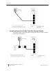
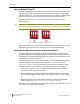
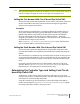
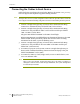

Table Of Contents
- Sensys Networks VDS240 Wireless Vehicle Detection System
- Access Point Controller Card (APCC) Installation Guide
- Contents
- Introduction
- Overview
- Access Point Controller Card (APCC)
- Types of APCC Configurations
- APCC Package Contents
- SPP Package Contents
- Additional Parts and Equipment Required
- 1. Cabling – a minimum of one straight-through Ethernet cables are required.
- 2. Laptop PC and TrafficDOT software – if contact closure cards will be configured via TrafficDOT's GUI, a suitable host is required.
- 3. Contact closure card functions can be configured from the switches on the front panel eliminating the need for a laptop PC and TrafficDOT.
- APCC Installation Considerations
- SPP Installation Considerations
- APCC Installation Procedures
- SPP Installation Procedures
- Tools Required for SPP Installation
- Step-by-Step Procedures
- Installing the Mounting Plate on Poles
- Installing the Mounting Plate on Walls
- Installing the Mounting Plate on Beams
- Determining the Type of SPP Radio Bulkhead Connector
- Connecting the Cable to an SPP Radio with the Hex-head Connector
- Step-by-Step Procedures
- Figure 6.6. Remove the factory-installed cap
- Figure 6.7. Inspect the factory-installed gasket
- Figure 6.8. Replace damaged or used gaskets
- Figure 6.9. Thread cable through connector A
- Figure 6.10. Thread cable through connector B
- Figure 6.11. Ethernet cable bushing chart (not to scale)
- Figure 6.12. Fit bushing onto cable between connector A and connector B
- Proper Fit (little to no gap between edges of cut)
- Improper Fit (gap between edges of cut)
- Proper Fit (bushing fully seated into guides)
- Improper Fit (bushing poorly seated into guides)
- Proper Fit (recessed bushing, smooth face)
- Improper Fit (bushing not recessed, pinched edge, mushroomed face)
- Removing the Cable Connection
- Configuration
- Overview
- Configuring Channels With the Front-Panel Interface
- Starting TrafficDOT and Connecting to an APCC
- Configuring Channels with TrafficDOT
- Defining Sensor-to-Channel Mappings
- Exiting TrafficDOT
- X Mode LED Displays for Slot Numbers
- Circuit-board Dip Switch SW1 Settings
- Circuit-board Dip Switch SW2 Settings
- Pre-Installation Worksheets
- Contact Closure Card External Interfaces

APCC Installation Procedures
Access Points Controller Card (APCC) 19
Sensys Networks, Inc. Installation Guide
NOTE:
After the cabinet backplane is queried for an address, be sure to take the APCC card out of
X-mode by setting front-panel dip switch 2 to the right, and resetting the card.
Setting the Slot-Number With Circuit-board Dip Switch SW2
Circuit-board dip switch SW2 implements the slot number component of the Card
ID. Set switch SW2 to match the value derived from the figure in Appendix A
subject to the exception noted below.
Exception
In cases where the controller does not assign an address, the installer will see a
front-panel channel LED display pattern indicating an address of 15 (all LEDs
lighted). This address can be used for the first contact closure card installed.
However, subsequent cards must be given a different address – arbitrarily
assigned by the installer. Any value between 0 and 15 may be used; remember that
Card IDs must be unique for the network.
Refer to
Appendix C: Circuit-board Dip Switch SW2 Settings for a figure that illustrates
how to set switch SW2 to values between 0 and 15.
Setting the Shelf-Number With Circuit-board Dip Switch SW1
Circuit-board dip switch SW1 implements the shelf number component of the
Card ID. Shelf numbers are assigned by the installer after visually inspecting the
cabinet.
The convention is to consider the top-most shelf in the card rack as shelf zero and
to increment the shelf number by one for each shelf below the top-most shelf. For
example, the bottom shelf in a cabinet of four shelves would be considered shelf
three.
Set circuit-board dip switch SW1 to the shelf number using the two left-most
switches. Refer to
Appendix B: Circuit-board Dip Switch SW1 Settings for a figure that
illustrates how to set switch SW1 to values between 0 and 3.
Determining the Controller Type and Setting it via Circuit-
board Dip Switch SW1
At the factory, contact closure cards are set for use with Type 170, Type 2070
(without status relays), or NEMA TS1 traffic controllers. This setting is made with
switch three of circuit-board dip switch SW1.
Verify the controller type and set dip three of circuit-board dip switch SW1 as
needed. Use the figure in
Appendix B: Circuit-board Dip Switch SW1 Settings as a guide
for setting switch three of SW1 to the proper value.