
Installation Guide
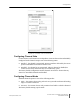
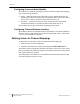
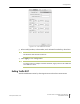

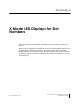
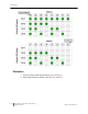

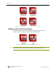
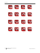
Table Of Contents
- Sensys Networks VDS240 Wireless Vehicle Detection System
- Access Point Controller Card (APCC) Installation Guide
- Contents
- Introduction
- Overview
- Access Point Controller Card (APCC)
- Types of APCC Configurations
- APCC Package Contents
- SPP Package Contents
- Additional Parts and Equipment Required
- 1. Cabling – a minimum of one straight-through Ethernet cables are required.
- 2. Laptop PC and TrafficDOT software – if contact closure cards will be configured via TrafficDOT's GUI, a suitable host is required.
- 3. Contact closure card functions can be configured from the switches on the front panel eliminating the need for a laptop PC and TrafficDOT.
- APCC Installation Considerations
- SPP Installation Considerations
- APCC Installation Procedures
- SPP Installation Procedures
- Tools Required for SPP Installation
- Step-by-Step Procedures
- Installing the Mounting Plate on Poles
- Installing the Mounting Plate on Walls
- Installing the Mounting Plate on Beams
- Determining the Type of SPP Radio Bulkhead Connector
- Connecting the Cable to an SPP Radio with the Hex-head Connector
- Step-by-Step Procedures
- Figure 6.6. Remove the factory-installed cap
- Figure 6.7. Inspect the factory-installed gasket
- Figure 6.8. Replace damaged or used gaskets
- Figure 6.9. Thread cable through connector A
- Figure 6.10. Thread cable through connector B
- Figure 6.11. Ethernet cable bushing chart (not to scale)
- Figure 6.12. Fit bushing onto cable between connector A and connector B
- Proper Fit (little to no gap between edges of cut)
- Improper Fit (gap between edges of cut)
- Proper Fit (bushing fully seated into guides)
- Improper Fit (bushing poorly seated into guides)
- Proper Fit (recessed bushing, smooth face)
- Improper Fit (bushing not recessed, pinched edge, mushroomed face)
- Removing the Cable Connection
- Configuration
- Overview
- Configuring Channels With the Front-Panel Interface
- Starting TrafficDOT and Connecting to an APCC
- Configuring Channels with TrafficDOT
- Defining Sensor-to-Channel Mappings
- Exiting TrafficDOT
- X Mode LED Displays for Slot Numbers
- Circuit-board Dip Switch SW1 Settings
- Circuit-board Dip Switch SW2 Settings
- Pre-Installation Worksheets
- Contact Closure Card External Interfaces

Chapter 7
44 Access Point Controller Card (APCC)
Installation Guide Sensys Networks, Inc.
Configuring Presence Mode Modifier
The behavior of a channel operating in presence mode may adjusted by applying
one of the following modifiers:
Delay – defers the onset of the contact closure by a specified duration. If a
vehicle moves off of the sensor before the specified delay expires, the contact
does not close. Delay is expressed in seconds from zero to 31.
Extension – increases the duration of the contact closure by a specified
increment. Extension is expressed in half-seconds from zero t0 7.5.
The modifiers do not apply to channels operating in pulse mode.
Configuring Channel Holdover Duration
The Channel Holderover parameter allows an extension to the channel holdover
duration when it is activated by the events from a particular sensor. Values from
0.0 to 0.75 are available for selection.
Defining Sensor-to-Channel Mappings
To map sensors to an APCC or EX card, perform the following steps:
1. Select a sensor from the image map.
2. Open the Card Addresses window by clicking the Card Addresses tab.
The Extension entry extends the duration of an APCC or EX card on a per-sensor
basis. The Delay entry delays the duration of an APCC or EX card on a per-sensor
basis; these entries are optional.
The shelf number-slot number is a card address associated with an APCC or EX
card, and channel is between 1 and 4.