
Installation Guide
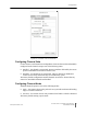
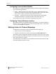
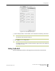

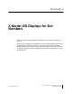
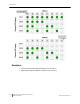

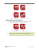
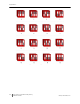
Table Of Contents
- Sensys Networks VDS240 Wireless Vehicle Detection System
- Access Point Controller Card (APCC) Installation Guide
- Contents
- Introduction
- Overview
- Access Point Controller Card (APCC)
- Types of APCC Configurations
- APCC Package Contents
- SPP Package Contents
- Additional Parts and Equipment Required
- 1. Cabling – a minimum of one straight-through Ethernet cables are required.
- 2. Laptop PC and TrafficDOT software – if contact closure cards will be configured via TrafficDOT's GUI, a suitable host is required.
- 3. Contact closure card functions can be configured from the switches on the front panel eliminating the need for a laptop PC and TrafficDOT.
- APCC Installation Considerations
- SPP Installation Considerations
- APCC Installation Procedures
- SPP Installation Procedures
- Tools Required for SPP Installation
- Step-by-Step Procedures
- Installing the Mounting Plate on Poles
- Installing the Mounting Plate on Walls
- Installing the Mounting Plate on Beams
- Determining the Type of SPP Radio Bulkhead Connector
- Connecting the Cable to an SPP Radio with the Hex-head Connector
- Step-by-Step Procedures
- Figure 6.6. Remove the factory-installed cap
- Figure 6.7. Inspect the factory-installed gasket
- Figure 6.8. Replace damaged or used gaskets
- Figure 6.9. Thread cable through connector A
- Figure 6.10. Thread cable through connector B
- Figure 6.11. Ethernet cable bushing chart (not to scale)
- Figure 6.12. Fit bushing onto cable between connector A and connector B
- Proper Fit (little to no gap between edges of cut)
- Improper Fit (gap between edges of cut)
- Proper Fit (bushing fully seated into guides)
- Improper Fit (bushing poorly seated into guides)
- Proper Fit (recessed bushing, smooth face)
- Improper Fit (bushing not recessed, pinched edge, mushroomed face)
- Removing the Cable Connection
- Configuration
- Overview
- Configuring Channels With the Front-Panel Interface
- Starting TrafficDOT and Connecting to an APCC
- Configuring Channels with TrafficDOT
- Defining Sensor-to-Channel Mappings
- Exiting TrafficDOT
- X Mode LED Displays for Slot Numbers
- Circuit-board Dip Switch SW1 Settings
- Circuit-board Dip Switch SW2 Settings
- Pre-Installation Worksheets
- Contact Closure Card External Interfaces

Access Point Controller Card (APCC) 47
Sensys Networks, Inc. Installation Guide
Appendix A
X Mode LED Displays for Slot
Numbers
This appendix depicts the channel LED displays when an APCC operates in X
mode.
When a card is configured in X mode, the front-panel channel LEDs display one of
the patterns shown in the figure below. Match the pattern of the front-panel
channel LEDs to a pattern in the figure. Use the corresponding value found under
the heading Address as the slot-number portion of the Card ID. (Refer to
Examples
after the figure.)