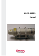
LMC-J-0050-3 Manual
Dear User You are advised to carefully read this User Manual before powering on the LMC J 0050 3 laser distance measuring module for the first time. This is necessary to ensure that you will be able to utilize all the capabilities and features which your new acquisition provides. This technology is subject to continuously ongoing development. Revision state: Date Revision February 2009 003 IMJ00503 V3E.DOC Explanation Compiled Page 2 of 40 19.02.
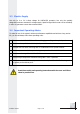
For highlighting purposes, the following pictograms, signs of reference and warning symbols are used throughout this Manual: Enumeration + Advice/Important/Important Note ® Reference (to a passage of text or a Figure) Warning symbols Warning: Indicates potential health risks that may occur if symbols of this type are disregarded. Caution: Warns of potential product damage. Laser: Warns of potential exposure to emerging visible or invisible laser radiation.
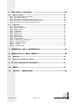
Content 1. GENERAL ..................................................................................................... 6 2. SAFETY INSTRUCTIONS .............................................................................. 6 2.1 Basic Notes ..................................................................................................................... 6 2.2 Laser Classification......................................................................................................... 6 2.
6. LMC-J-0040-3 OPERATION .......................................................................29 6.1 Measuring Modes .......................................................................................................... 29 6.1.1 DM: Single Distance Measurement ..................................................................................... 29 6.1.2 DT: Distance Tracking ....................................................................................................... 29 6.1.
1. General The LMC J 0050 3 is an opto electronic distance measuring module for industrial applications. Equipped with a Profibus® DP interface, the LMC J 0050 3 can easily be integrated into any fieldbus driven process controller. The additional SSI interface provides another convenient option for controlled operation of the measuring module.
2.3 Electric Supply Use only 10 V to 30 V direct voltage for LMCJ00503 operation. Use only the specially designated connector terminal for voltage supply. Specified signal levels must not be exceeded, in order to guarantee correct data communication. 2.
3. INTENDED & CONFORMING USE 3.1 General Product Description The LMC J 0050 3 is a laser distance measuring module to determine distances from 0.1 m to 30 m, using natural surfaces, or to measure distances up to 150 m with a target reflector. Providing a red laser sighting point, the LMCJ0050 3 allows you to unequivocally mark a particular target. Its effective operating range depends on the reflectance and surface qualities of the targets being sighted.
3.2 Conforming Use Measurement of distances and output of measured data to the Profibus. Special measuring functions. Compliance with prescribed temperatures for operation and storage. Operation at correct voltage level. Application of specified signal levels to the appropriate data lines. 3.3 Nonconforming Use Do not operate the LMC J 0050 3 in any other way than described under “Intended & Conforming Use“ above and only in a proper working condition.
4. Product Description 4.1 Scope of Delivery Description Part number LMC J 0050 3 LMC.00798 CD with Customer documentation 2m cable LMC.00486 5m cable LMC.00487 10m cable LMC.00488 Socket 12 poles LMC.00546 End ressistance PB M12 LMC.00644 PB socket 5 polig LMC.00645 PB plug 5 poles LMC.00646 PB In/Out cable 5m; LMC PB IN/OUT/5M LMC.00923 PB In cable 5m; LMC PB IN/5M LMC.00647 PB IN cable 10m; LMC PB IN/10M LMC.00649 PB Out cable 5m LMC.00650 PB Out cable 10m LMC.
4.2 Technical Data Measuring Performance Measuring principle Comparative phase measurement Measuring parameter Distances Measuring range*1 0.1 m ... 30 m for natural, diffusely reflecting surfaces, and up to 150 m with a target board Measuring accuracy ± 2 mm for white surfaces, (+15 °C ... +30 °C) ± 3 mm for natural surfaces, (+15 °C ... +30 °C) Target surface Of natural, diffusely reflecting type Target board required From 30 m to 150 m Measured resolution value 0.1 mm Reproducibility <+-0.
Interface Data interface Profibus RS485 . Ident. no. 0x09CB Profibus DP V0 slave under IEC 61158 / IEC 61784 External termination resistor Baud rate 9.6 / 19.2 / 93.75 / 187.5 / 500 kbaud 1.5 / 3 / 6 / 12 Mbaud Automatic baud rate detection GSD file LMCJ40_3.GSD PNO Profile Encoder Class 1/2. Configuration of measuring parameters. Output of measured values and error messages Parameters and PB address are stored in NVRAM SSI interface Transfer rate: 50 kHz ...
4.3 Mechanical Mounting Conditions The casing consists of a rugged, corrosion resistant extruded aluminum profile with front side and rear side covers also in corrosion resistant design. Four mounting holes are provided in the baseplate for mechanical attachment of the LMC J 0050 3. ( Fig. 1 Dimensional drawing type A an B ). Type: A Type: B Abb. 1: LMC J 0050 3 IMJ00503 V3E.DOC Page 13 of 40 19.02.
4.4 Connector Pin Assignments white brown green Power 10V .... 30V green yellow red gray orange blue red black green violet white/brown red white/black Device Terminal Fig. 3: Pinning diagram For operation via Profibus, other Profibus participants may connect to the 5 pole jack (A wire, B wire). The Profibus may terminate or continue at the 5 pole connector. Some kind of termination device must always be provided at the end of the Profibus.
4.5.4 Slave Address A Profibus address can be assigned, with due consideration of other participants in bus communications, to any number from 0 to 125. The setting of an address can be achieved by triggering an SSA command via the Profibus. For details on how to change a previously set slave address via the configuring tool, you should consult the special tool documentation. In as delivered state, the slave is set to the address “4”. A currently set slave address is permanently stored in the EEPROM.
4.5.7 Segment Length The maximum segment length between Profibus participants depends on the selected baud rate. The following segment length requirements must be met: Baud rate [baud] Segment length [m] 9.6 k – 93.75 k 1200 187.5 k 1000 500 k 400 1.5 M 200 3 M – 12 M 100 For cabling in accordance with these segmenting limits, you are stongly recommended to use cable of type A. This cable type provides the following performance features: Surge impedance 135 ...
4.5.8 Wiring Diagram white green brown green red yellow gray orange blue red Power Supply black violet white/brown green white/black red Device Terminal Fig. 4: Minimum wiring configuration of Profibus interface IMJ00503 V3E.DOC Page 17 of 40 19.02.
4.5.9 Description of the ProfiBus Interface 4.5.9.1. General Information The Profibus Interface for LMC J 0050 3 operation control is identical with the Standard DP V0 Profibus (with peripherals decentralized) where V0 designates the version. Telegrams are byte oriented. A byte is also referred to as an Octet in Standard Profibus terminology.
4.5.9.4. Configuration Data For input and output data, the following configurations are available: mandantory class 1 class 2 D1 hex F1 hex 2 words inputs consistency 2 words of input data, 2 words of output data for preset value, consistency optional class 1 class 2 D0 hex F0 hex Not implemented in LMCJ0043 Not implemented in LMCJ0043 4.5.9.5. Cyclical Data Exchange – Input (Slave > Master) The LMC J 0050 3 outputs position data which are mathematically signed.
4.5.9.1Parameter data The following minimum parameter setups apply to class 1 devices: Octet 1 2 3 4 5..
4.5.9.2Diagnostic data Class 2 functionality Commissioning diagnostic 0 1 1 0 1 Octet 1 2 3 4 5..
10 11 12 bool bool bool 13 bool 14 15 bool bool word word word word unsigned 32 signed 32 signed 32 unsigned 32 unsigned 32 10 byte word signed byte byte 20..21 22..23 24..25 26..27 28..31 32..35 36..39 40..43 44..47 48..57 58..59 60 61 E54: hardware error (PLL) E55: hardware error E61: selected parameter is illegal; invalid command was triggered E62: 1. hardware error 2. false value for interface communications (parity error SIO) E63: overflow SIO E64 . framing error SIO warnings .
4.6 SSI Interface Parameter settings for SSI interface operation can be made via the Profibus. Default state set on initial product delivery: DT Mode. The LMC J 0050 3 has a SSI data interface (SSI = synchronous serial interface). At the request of a SSI clock generator, the LMCJ0050 3 triggers a distance measurement cycle, sending the data bit by bit to a controller for processing in the same order as it arrives at the shift register.
For SSI interface operation, the wiring diagram is as follows: white brown PLC green yellow gray orange blue Power Supply red black violet white/brown white/black Fig. 5: Wiring for SSI interface operation 4.7 Alarm Outputs Parameter settings for alarm outputs can be made via Profibus. This function is only available with the Profibus in active state. Each of the two alarm outputs allows a given object or state to be monitored for positive or negative excession of its limit values.
Distance Distance Fig. 6: Digital switching output behaviour for positive and negative hysteresis. LOW corresponds to a voltage level < 2 V. HIGH corresponds to a voltage level of VCC 2 V. Each alarm output is short circuit proof and rated for a maximum current load of 0.5 A. Parameter settings for alarm outputs can be made with the Profibus master, using the Encoder profile with Class 1 functionality.
The wiring diagram for utilization of alarm outputs is as follows: white green brown green Setup red yellow gray orange blue red Power Supply black violet white/brown Control white/black Device Terminal green red Fig. 7: Wiring for alarm outputs 4.8 Trigger Input Parameter settings for the trigger input can be made using Profibus tools. This function is only enabled with the Profibus in active state.
The following parameters are available for configuration (refer to GSD File): ExtUserPrmData = 20 “Trigger Mode” for trigger mode ExtUserPrmData = 21 “Trigger Level” for trigger level ExtUserPrmData = 25 “Trigger Delay (31 16)” for trigger delay ExtUserPrmData = 26 “Trigger Delay (15 0)” for trigger delay For detection of a clock edge, the following voltage signals are required: 24 V > HIGH > 11 V 0 V < LOW < 6.
4. Start-Up The table below proposes a sample procedure that may be followed for LMC J 0050 3 start up. It does not purport to provide complete information or exhausting details on all possible applications. For this description, it is assumed that the user will match cabling to his/her specific requirements.
5. LMC-J-0050-3 Operation 6.1 Measuring Modes The various measuring modes are distinguished by the algorithms they use for calculation. The LMC J 0050 3 relies on the phase comparison method for normal operation. In order to obtain a precise measured value, the user should perform an appropriate number of single distance shots at different frequencies of a fixed number.
Desired settings for the Measuring Time, the trigger edge (“Trigger Level”) and the delay in triggering (“Trigger Delay”) can be made in the Master’s configuring tool, using the Encoder profile and Class 2 encoder functionality. Trigger mode must be active. 6.2 Parameters Settings can be made for each parameter in the Master configuration tool, using the Encoder profile and Class 2 encoder functionality. For a description, you should refer to the special configuring tool documentation.
6.2.7 Error Reaction Error Reaction defines how the alarm outputs will react if a measurement cycle is found to have been unsuccessful. Different setting options are available in order to cause error messages to trigger different kinds of response as appropriate for a particular environment in which the LMC J 0040 3 operates.
6.2.10 Switching Point Output 1 or 2 Switching Point Output 1 or 2 corresponds to the trigger threshold of alarm output 1 or 2 respectively. The trigger threshold behaviour is user-definable. For settings of this kind, a switching hysteresis parameter is provided (refer to section 6.2.11). 6.2.11 Hysteresis Output 1 or 2 Hysteresis Output 1 or 2 corresponds to the switching hysteresis of alarm output 1 and 2 respectively.
6.2.13 Average Average allows a floating mean value to be calculated from one to twenty measured single values. Calculation is based on this formula: Mean value x = x1 + x2 + x3 + ... + xn (20) n 6.2.
6. Preventive Care & Maintenance Please note: To remove dust from optical glass surfaces (of transmitter or receiver optics), you may use a pneumatic brush. Do not use solvent containing cleaners to wipe optical surfaces down. You are advised to contact the Manufacturer if there is contamination of a more obstinate nature. Refrain from the use of solvents for cleaning work. You are prohibited from opening the LMC J 0050 3. Do not release any screws of the LMC J 0050 3.
7. Malfunction & Error Reports 8.1 Malfunction Error situation Cause Action for removal No data coming via Faulty Profibus configuration Profibus Check Profibus configuration Device error diagnosis) Reship LMC J 0050 3 for contact technical support (Ext. Hardware problems repair, 8.2 Errror Report Outputs via Profibus Code Cause Action for removal E15 Excessively poor reflexes Use target board, observe minimum requirement on measuring distance (> 0.
E53 Hardwarefehler Reship LMC J 0050 3 for repair Contact technical support E54 Hardware error Reship LMC J 0050 3 for repair Contact technical support E55 Hardware error Reship LMC J 0050 3 for repair Contact technical support E61 Hardware error Service required if occurring repeatedly, Reship LMC J 0050 3 for repair E62 Hardware error Check PB settings; if fault persists, reship LMC 0050 3 for repair, Contact technical support E63 SIO overflow Check time of emitted signals in application
8.
9.
10. Contact Information Sentek Solutions Ltd 1010 Cambourne Business Park, Cambridge, CB23 6DP Info@sentekeurope.com www.sentekeurope.