MODEL 5000 SENTRY GAS MONITORING SYSTEM Version 6 APPLICABILITY & EFFECTIVITY Effective for all Sentry systems manufactured after September 1, 1995.
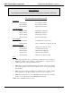
SMC sierra monitor corporation Sentry Instruction Manual - Version 6 FMRC APPROVAL ONLY THE FOLLOWING ITEMS, FUNCTIONS AND OPTIONS ARE FMRC* APPROVED Sentry Model 5000 Gas Monitoring System Controllers Model 5000-02 Two Channel Controller Model 5000-04 Four Channel Controller Model 5000-08 Eight Channel Controller Controller Options: Model 5380-00 Rack Mount Configuration Model 5383-00 NEMA-4X Configuration Model 5387-00 Printer Output Software Model 5392-00 Individual Alarm Relays Sensor M
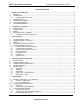
SMC sierra monitor corporation Sentry Instruction Manual - Version 6 TABLE OF CONTENTS 1. PRODUCT DESCRIPTION ............................................................................................................................................. 1 1.1 GENERAL....................................................................................................................................................................... 1 1.2 CONTROLLER ..........................................................
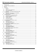
SMC sierra monitor corporation 6. 6.1 7. Sentry Instruction Manual - Version 6 MAINTENANCE .............................................................................................................................................................53 MAINTENANCE REQUIREMENTS...........................................................................................................................53 SERVICE......................................................................................................
SMC sierra monitor corporation 8. Sentry Instruction Manual - Version 6 APPENDICES.................................................................................................................................................................. 83 8.1 APPENDIX A - SPECIFICATIONS ............................................................................................................................. 85 8.2 APPENDIX B - LIMITED WARRANTY .................................................................
SMC sierra monitor corporation Sentry Instruction Manual - Version 6 1. PRODUCT DESCRIPTION 1.1 GENERAL The Sentry 5000 is a fixed installation gas monitoring system designed for continuous operation in open or confined areas. The system is comprised of a controller and up to eight sensor modules. The sensor modules are supplied for detection of combustible gas, oxygen deficiency or various toxic gases and can be mixed within one system as required. 1.
SMC sierra monitor corporation Sentry Instruction Manual - Version 6 1.4 INTERCONNECT WIRING Not supplied with Sentry, but necessary to the installation and operation is the three conductor wiring which connects the controller to the modules. Before this wiring is installed it is important to read and understand the installation instructions (Chapter 3) because significant economies can be realized by connecting more than one module onto a common wiring run.
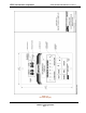
SMC sierra monitor corporation Sentry Instruction Manual - Version 6 Figure 1-1 Front Panel Display PRODUCT DESCRIPTION Page: 3
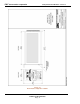
SMC sierra monitor corporation Sentry Instruction Manual - Version 6 Figure 1-2 Rack Mount Configuration - Outline PRODUCT DESCRIPTION Page: 4
SMC sierra monitor corporation Sentry Instruction Manual - Version 6 Figure 1-3 NEMA-4 Configuration - Outline PRODUCT DESCRIPTION Page: 5
SMC sierra monitor corporation Sentry Instruction Manual - Version 6 Figure 1-4 NEMA-7 Configuration - Outline PRODUCT DESCRIPTION Page: 6
SMC sierra monitor corporation Sentry Instruction Manual - Version 6 Figure 1-5 Panel Mount Configuration Outline PRODUCT DESCRIPTION Page: 7
SMC sierra monitor corporation Sentry Instruction Manual - Version 6 Figure 1-6 Wall Mount Configuration Outline PRODUCT DESCRIPTION Page: 8
SMC sierra monitor corporation Sentry Instruction Manual - Version 6 Figure 1-7 Hydrogen Sulfide Module - Outline PRODUCT DESCRIPTION Page: 9
SMC sierra monitor corporation Sentry Instruction Manual - Version 6 Figure 1-8 Combustible Sensor - Outline PRODUCT DESCRIPTION Page: 10
SMC sierra monitor corporation Sentry Instruction Manual - Version 6 Figure 1-9 Oxygen and Toxic Sensor Modules - Outline PRODUCT DESCRIPTION Page: 11
SMC sierra monitor corporation Sentry Instruction Manual - Version 6 Figure 1-10 Model 5100-05 Hydrogen Sulfide Sensor Module (FMRC Approved) - Outline PRODUCT DESCRIPTION Page: 12
SMC sierra monitor corporation Sentry Instruction Manual - Version 6 Figure 1-11 Model 5100-25 Ammonia Sensor Module - Outline PRODUCT DESCRIPTION Page: 13
SMC sierra monitor corporation Sentry Instruction Manual - Version 6 2. CAUTIONS & WARNINGS 2.1 INTRODUCTION 2.4 SENSOR MODULES - GENERAL Although the Sentry system is designed and constructed for installation and operation in industrial applications including "hostile" environments, caution should be taken to insure that the installation is made in compliance with this instruction manual and that certain procedures and conditions are avoided. This chapter discusses the necessary cautions.
SMC sierra monitor corporation Sentry Instruction Manual - Version 6 3. INSTALLATION NOTE All systems are factory are pre-configured and calibrated. All sensors are tagged to indicate the controller (alpha) and the sensor module number (1 - 8). Identify all components of the system during unpacking and install using the factory configuration. The system will power up in a calibrated and fully functional condition. • Modules should be placed close to the potential source of gas.
SMC sierra monitor corporation Sentry Instruction Manual - Version 6 Install conduit as required. Provide for splice boxes where multiple modules will be wired to a single run. Pull 3 (typical: white, black, green) conductors of the correct gauge wire from the controller to each splice box and from the respective splice box to each planned module location. See Figure 3-5 for proper wire termination in the splice box. Twisted wire secured with wire nuts is not an acceptable splice.
SMC sierra monitor corporation Sentry Instruction Manual - Version 6 3.5.2.2 CHASSIS MOUNTED CONTROLLER 3.5 CONTROLLER INSTALLATION 3.5.1 CONTROLLER CONFIGURATIONS Table 3-5 lists the number of sensor modules which can be operated on each controller model. Model Controller Capacity 5000-02 2 Sensor Modules 5000-04 4 Sensor Modules 5000-08 8 Sensor Modules The chassis mounted controller is provided with a preinstalled bezel and a template for the chassis cut-out.
SMC sierra monitor corporation • Sentry Instruction Manual - Version 6 Connect the necessary remote audible and visual alarms or other process control equipment to the "HIGH", "LOW" and "TROUBLE" dry contact relays on the connector panel. The Double Pole/Double Throw (DPDT) relay connections are marked to indicate Normally Open (N/O) , Normally Closed (N/C) and Common (COM) terminals for each pole. No voltage is applied to the terminals internally. Typical wiring configuration is described in Figure 3-11.
SMC sierra monitor corporation Sentry Instruction Manual - Version 6 3.5.6 POWER UP Systems shipped complete from the factory are preconfigured and calibrated. When power is turned on the power light will start flashing and the alpha-numeric display will indicate "SYSTEM WARM-UP" "PLEASE WAIT MM:SS" (where MM:SS is a five minute count-down clock). When the warm-up ends the two displays will begin functioning in the "continuous scan" mode which is described in the next chapter.
SMC sierra monitor corporation Sentry Instruction Manual - Version 6 Figure 3-2 Controller Mounting Options Page: 22
SMC sierra monitor corporation Sentry Instruction Manual - Version 6 Figure 3-3 Sensor Module Mounting Page: 23
SMC sierra monitor corporation Sentry Instruction Manual - Version 6 Figure 3-4 Wiring Options Page: 24
SMC sierra monitor corporation Sentry Instruction Manual - Version 6 Figure 3-5 Typical Splice Box Wiring Page: 25
SMC sierra monitor corporation Sentry Instruction Manual - Version 6 Figure 3-6 Sensor Module Cross Section Page: 26
SMC sierra monitor corporation Sentry Instruction Manual - Version 6 Figure 3-7 Sensor Module Connector Detail Page: 27
SMC sierra monitor corporation Sentry Instruction Manual - Version 6 Figure 3-8 Sensor Module Top Plate Detail - Typical Page: 28
SMC sierra monitor corporation Sentry Instruction Manual - Version 6 Figure 3-9 Controller Connector Panel - Rack Configuration Page: 29
SMC sierra monitor corporation Sentry Instruction Manual - Version 6 Figure 3-10 Controller Connector Panel - NEMA-4X Configuration Page: 30
SMC sierra monitor corporation Sentry Instruction Manual - Version 6 Figure 3-11 Typical Alarm Wiring Configuration Page: 31
SMC sierra monitor corporation Sentry Instruction Manual - Version 6 4. CONFIGURATION PROCEDURE 4.1 INTRODUCTION If the ENTER key is pressed once during normal operation the display locks onto the current module number and can be advanced using the UP and DOWN arrow keys. When the display is locked onto one module number the gas type and units display is shown in round parenthesis “( )”. Sentry is operated via the seven keys on the front panel.
SMC sierra monitor corporation MODULE ADDRESS LOCATION Sentry Instruction Manual - Version 6 SENTRY CHANNEL GAS TYPE LOW HIGH LATCH SCALING FACTORS SENSOR SERIAL # 1 2 3 4 5 6 7 8 Figure 4-1 System Configuration Worksheet NOTES 1 Module Address Dip switch setting for each sensor module 2 Location Describe the physical location of the module 3 Sentry Channel Log the channel number to which the module is wired 4 Gas Log the name of the gas which is to be detected 5 Low Alarm Enter th
SMC sierra monitor corporation Sentry Instruction Manual - Version 6 4.3 CONFIGURATION INSTRUCTIONS Sentry controllers which are components of complete systems are factory configured and generally do not require changes prior to being placed in service. Sentry controllers which have not been factory configured can be placed into operation with default values for all configuration parameters by using the diagnostic code “0021” described in Section 8.3 of this manual.
SMC sierra monitor corporation Sentry Instruction Manual - Version 6 In NORMAL OPERATE mode Sentry scans all modules in sequence and displays their current readings. For any modules which are not correctly initiated and calibrated the status will be indicated. This scanning sequence is by module number by type.
SMC sierra monitor corporation Sentry Instruction Manual - Version 6 − Lowest concentration LC with date and time 4.5 SENTRY MENU Table 4-2 describes the primary activities that can be accessed via the Sentry keyboard. Each activity which involves submenu selection is identified by an asterisk Menu selections which refer to printer are standard in eight channel systems, optional in two and four channel systems. The MODBUS option replaces Printer software.
SMC sierra monitor corporation Sentry Instruction Manual - Version 6 4.5.3.5 EXTERNAL RESET KEY 4.5.2.5 SET DATE/TIME The external RESET key on NEMA units implements RESET ALARMS and eliminates the need to open the enclosure for this purpose. PRESS ENTER TO SET DATE & TIME Set the Sentry clock in the same manner as any digital clock is set. The format is MM/DD HH:MM, with the hours set in military time (24 hours). If a user code has been set-up it will be required prior to changing the clock.
SMC sierra monitor corporation Sentry Instruction Manual - Version 6 4.6 SET USER CODE When the OPERATE MODE is selected by pressing ENTER the Change/Calibrate light turns off and Sentry returns to the pre-selected scanning mode. PRESS ENTER TO SET USER CODE 4.6.2 MODE KEY - OTHER To avoid unauthorized access to the configuration activity the USER CODE should be set as soon as the Sentry has been put on line. User codes are described in Section 8.3.
SMC sierra monitor corporation Sentry Instruction Manual - Version 6 4.6.2.2 CHECK CALIB PRESS ENTER T O: CHECK CALIB The present calibration parameters can be check by successive presses of the ENTER key. These include the gas type, full scale, concentration of calibration gas, the number of days between calibrations and the status of global calibrate. 4.6.2.3 CHECK MODULE PRESS ENTER TO: CHECK MODULE Any module number can be selected and configuration information for that module recalled.
SMC sierra monitor corporation Sentry Instruction Manual - Version 6 SENTRY KEY BOARD Ts = TEST R = RESET M = MODE T = TIME ^ = ARROWS * GLOBAL CALIBRATION RESET KEY Reset Alarms R E Reset System R R E Reset History R R R E TIME KEY Check History E = ENTER T E Printer History T T E Print System T T T E Print Status T T T T E Set Date & Time T T T T T Gas Type (Concentration) ^ Enter to Span E Apply Zero Gas E Enter to Span E Apply Span Gas E Operate Mode
SMC sierra monitor corporation Sentry Instruction Manual - Version 6 OPERATE MODE RESET RESET ALARMS ENTER ALARMS RESET OPERATE MODE ENTER SYSTEM RESET OPERATE MODE ENTER CODE? RESET RESET SYSTEM RESET RESET HISTORY Y RESET N N VALID Y ACCESS DENIED RESET HISTORY RETURN TO OPERATE MODE Figure 4-3 Sentry Reset Key Flow Chart CONFIGURATION PROCEDURE Page: 42 RESET COMPLETE
SMC sierra monitor corporation Sentry Instruction Manual - Version 6 OPERATE MODE TEST TEST SYSTEM ENTER SYSTEM TEST FUNCTIONS TEST TEST ALARMS ENTER CODE? SENTRY REV # IDENTIFIERS Y TEST N VALID PASSIVE LOW ALARM Y ACCESS DENIED ACTIVE LOW ALARM PASSIVE HIGH ALARM ACTIVE HIGH ALARM PASSIVE TROUBLE ACTIVE TROUBLE FULL DISPLAY TEST RETURN TO OPERATE MODE Figure 4-4 Sentry Test Key Flow Chart CONFIGURATION PROCEDURE Page: 43
SMC sierra monitor corporation Sentry Instruction Manual - Version 6 OPERATE MODE TIME CHECK HISTORY ENTER DATE & TIME HISTORY RESET TIME HISTORY REPORT ENTER TIME STATUS REPORT ENTER TIME SET DATE & TIME POWER DOWN POWER UP REPORT COMPLETE ENTER CHANGE MODULE NO. REPORT ENTER LOW ALARM D/T HIGH ALARM D/T REPORT COMPLETE ENTER LOWEST CONC. VALUE D/T REPORT ENTER HIGHEST CONC. VALUE D/T REPORT COMPLETE ENTER LAST CALIB.
SMC sierra monitor corporation Sentry Instruction Manual - Version 6 OPERATE MODE CODE N MODE CALIB OR CHANGE Y VALID ENTER N ACCESS DENIED ENTERS CHANGE MENU (MODE KEY ACTIVE)) MODE SELECT SCAN SELECT USING ARROWS ENTER CONTINUOUS SAFE SCAN HIGHEST SENSOR ENTER GAS, CONC, FULL SCALE FREQUENCY GLOBAL? ENTER ENTER MODULE #, ON/OFF ALARMS LATCH? ALARM VALUES FACTORS ENTER ENTER PRINTER ON/OFF CONTROLLER ID PRINT CONFIG.
SMC sierra monitor corporation OPERATE MODE CALIBRATE ** MODE MODE CALIB OR CHANGE CHANGE CALIBRATE ENTER MODE CODE CHANGE MODULE Y N Sentry Instruction Manual - Version 6 ENTER CALIBRATION PROCEDURE ENTER CHANGE CALIB PROCEDURE CALIBRATE ** ENTER MODULE CONFIG.
SMC sierra monitor corporation Sentry Instruction Manual - Version 6 5. CALIBRATION 5.1 SENTRY CALIBRATION - AN OVERVIEW • Individual modules can be calibrated while others remain on line. • Time savings when sensors must be exposed to zero air due to the environment. Calibration is a simple three step process: 1. Initiate calibration via the controller keyboard. 2. Apply zero gas (if required) and then span gas to the sensors. 3. Close the calibration via the controller keyboard.
SMC sierra monitor corporation Sentry Instruction Manual - Version 6 5.2.2 CALIBRATION PARAMETERS 5.3 CALIBRATION PROCEDURE Use the CHANGE CALIB menu to configure calibration parameters as follows: Calibration parameters remain in Sentry memory until changed by the operator, they do not require initiation at every calibration 5.3.
SMC sierra monitor corporation Sentry Instruction Manual - Version 6 5.3.1.1 GLOBAL CALIBRATION Step Proceed with the following steps to perform Global Calibration. Step 1 Activity Begin ZERO value read. application - no errors ENTER TO ZERO 1 2 3 4 5 6 7 8 2 Complete ZERO value read. 6 APPLY ZERO GAS ENTER WHEN DONE • Example "1. 00", "2 00" etc. 3 Begin SPAN value read 7 8 ENTER TO SPAN Press ENTER to begin the span process.
SMC sierra monitor corporation Sentry Instruction Manual - Version 6 5.3.1.2 LOCAL CALIBRATION Step Proceed with the following steps to perform Local Calibration Step Activity 1 Apply ZERO and SPAN gas to each sensor. & 50% LEL 1 2 3 4 5 6 7 8 2 2. Using the apparatus in Section XXX, thread the calibration head into the sensor assembly. At this time the controller top display will lock onto this module number.
SMC sierra monitor corporation Sentry Instruction Manual - Version 6 5.3.2 CALIBRATION GAS DELIVERY METHODS Calibration gas is can be delivered to the sensors via the following delivery devices: Model 5358-00: Calibration Adapter - used with portable calibrators. - See Figure 5-1 Model 5360-00: Calibration Gas Delivery fitting permanently installed fitting which allows tubing to be run to a convenient delivery location 5.3.
SMC sierra monitor corporation Sentry Instruction Manual - Version 6 6. MAINTENANCE 6.1 MAINTENANCE REQUIREMENTS The following are the manufacturer’s recommendations for periodic maintenance of the Sentry system: 1 CALIBRATION: All sensors should be calibrated at a minimum of every 90 days. NOTE FMRC approved combustible gas sensors are required to be calibrated every 90 days. 2 BATTERY REPLACEMENT: The lithium battery for memory retention should be replaced every two years.
SMC sierra monitor corporation Sentry Instruction Manual - Version 6 7. SERVICE electrical conduits and provide moisture traps and drains to avoid water damage 7.1 OVERVIEW 7.1.1 GENERAL • This section provides service information for Sentry systems which have software version 6.0 and above The section is intended for use by a qualified field technician. Sierra Monitor sales and technical staff are available to assist by telephone at (408) 262-6611, during normal west coast working hours. 7.1.2.
SMC sierra monitor corporation Sentry Instruction Manual - Version 6 INSPECTION GUIDE OPERATOR ACTION RESULT CORRECT, Incorrect TURN SYSTEM ON POWER LIGHT FLASHING Power light solid Power light off RESET/RESET/ENTER Reason/Correction Turn off & restart Check fuse & line voltage Check power supply 5v fuse POWER LIGHT SOLID Power light flashing & Top Display = “----" Top display = E1 Top display = E2 Top display blank System is re-setting, check for channel cable short EPROM error (fatal) RAM error
SMC sierra monitor corporation Sentry Instruction Manual - Version 6 TROUBLE SHOOTING GUIDE Symptom CONTROLLER Top Display: wrong characters displaying 8888 or Blank Bottom Display blank Diagnostic voltages displayed are more than 10% different from manual Keyboard: Wrong action based on key press Alarms intermittent or false AC fuse blows Modules not recognized MODULES Module not recognized Module recognized as wrong type Sensor failure Multiplexing problem PRINTER Not Printing Printing garbage Caus
SMC sierra monitor corporation Sentry Instruction Manual - Version 6 7.2.1.4 FRONT PANEL 7.2 CONTROLLER 7.2.1 MECHANICAL/FUNCTIONAL DESCRIPTION The controller consists of four sub assemblies. Figure 7-1. 7.2.1.1 CONNECTOR PANEL The Back Panel contains all the connectors for providing system power, powering and communicating with the modules, operating alarm devices and communicating with a printer. The panel also contains the AC fuse.
SMC sierra monitor corporation Sentry Instruction Manual - Version 6 • Action: check fuse F2 on power supply board. If power supply jumpers have been cut, cold start requires 110 VAC. • • 7.2.2.2 POWER SUPPLY ADJUSTMENTS The +24 volts can be measured at TP1 or TP2 (Test Point 1 or 2) with respect to ground (GT1). Figure 7-3. If there is no +24 volts and replace fuse F1 • • The +5 volts can be measured at TP4 If there is no +5 volts check and replace fuse F3. The +15 volts can be measured at TP5. 7.2.
SMC sierra monitor corporation Sentry Instruction Manual - Version 6 Figure 7-1 Controller Exploded View SERVICE Page: 60
SMC sierra monitor corporation Sentry Instruction Manual - Version 6 Figure 7-2 Control Board Component Locator SERVICE Page: 61
SMC sierra monitor corporation Sentry Instruction Manual - Version 6 Figure 7-3 Power Supply Component Locator SERVICE Page: 62
SMC sierra monitor corporation Sentry Instruction Manual - Version 6 The eight (total) signals are: 7.3 COMMUNICATIONS 7.3.1 DESCRIPTION OF COMMUNICATIONS • • The Sentry controller scans each channel in turn taking less than one second to scan all channels. At each channel: • 1. A "reset" signal is sent out to clear all module communications. 2. An address (which is a module number) is sent out and the controller waits for a response.
SMC sierra monitor corporation Sentry Instruction Manual - Version 6 7.3.2 WARNING AND ERROR MESSAGES 7.3.2.1 SYSTEM ERRORS If Sentry cannot operate the basic computer functions one of the System Errors listed in Table 7-1 will display. These failures indicate internal controller problems which are most likely to require board level repairs by the factory. All other modules on the channel and modules on other channels remain in full operation and continue to be scanned by the controller.
SMC sierra monitor corporation Sentry Instruction Manual - Version 6 7.3.6 DIAGNOSTIC REPORT A Diagnostic report can be printed using diagnostic codes 0008 or 0010. Figure 7-4 is a typical report.. ID:A 11/20 15:16 S1= +0.376 S2= +1.20 BV= +2.021 BI= 0.323 SP= 0653 ST= +0.284 MV= +19.0 CS= +0.000 HV= +0.920 HI= +0.975 SP= 400 ST= +0.009 MV= +19.4 CS= +0.
SMC sierra monitor corporation Sentry Instruction Manual - Version 6 7.4 HYDROGEN SULFIDE MODULE (5100-01) 7.4.1 DESCRIPTION The Hydrogen Sulfide Sensor Module includes the sensor and electronic assembly installed in an explosion proof housing. The sensor screws into one hub of the enclosure and plugs into the bottom electronics card via a six pin connector. Cabling to the controller connects to a three pin spring loaded terminal strip.
SMC sierra monitor corporation Sentry Instruction Manual - Version 6 To adjust the sensitivity apply 20 ppm hydrogen sulfide for five minutes for full stabilization. (Check that the voltage drops by at least .3 volts during this time.) Adjust the signal out value to .6 VDC using the range adjust potentiometer. Remove gas and verify that the voltage climbs to above 1.0 VDC in five minutes. 7.4.
SMC sierra monitor corporation Sentry Instruction Manual - Version 6 Heater Heater Heater Heater Heater Heater Heater Heater Voltage Current Voltage Current Voltage Current Voltage Current 2.50 3.32. 2.90 3.60 3.30 3.92 3.70 4.25 2.51 3.32 2.91 3.61 3.31 3.93 3.71 4.26 2.52 3.33 2.92 3.62 3.32 3.93 3.72 4.27 2.53 3.34 2.93 3.63 3.33 3.94 3.73 4.28 2.54 3.34 2.94 3.63 3.34 3.95 3.74 4.29 2.55 3.35 2.95 3.64 3.35 3.96 3.75 4.29 2.56 3.36 2.
SMC sierra monitor corporation 7.5 Sentry Instruction Manual - Version 6 COMBUSTIBLE GAS SENSOR MODULE (5100-02) 7.5.1 DESCRIPTION The Combustible Gas Module includes the sensor and electronic assembly installed in an explosion proof housing. The sensor screws into one hub of the enclosure and plugs into the bottom electronics card via a six pin connector. Cabling to the controller connects to a three pin spring loaded terminal strip. 7.5.
SMC sierra monitor corporation 3. 4. 5. Sentry Instruction Manual - Version 6 Using a Sierra Monitor Model 1200-26 Gas Calibrator with a Sierra Monitor Model 5358-00 calibration adapter, or Model 5360 Gas Delivery Fitting. Apply the calibration gas at a flow rate of 100 cc/min. until the signal out voltage stops changing (approx. 2 minutes). Then adjust span adj. potentiometer to the calculated value. PIN Remove the calibration gas and wait for the voltage to drop. If the voltage is below 0.
SMC sierra monitor corporation Sentry Instruction Manual - Version 6 7.5.
SMC sierra monitor corporation Sentry Instruction Manual - Version 6 7.6 OXYGEN MODULE (5100-03) 7.6.1 DESCRIPTION The Oxygen Module includes the electronic assembly installed in an explosion proof housing and the electrochemical sensor connected to one hub of the enclosure. Cabling from the controller connects to a three pin spring loaded terminal strip. 7.6.
SMC sierra monitor corporation Sentry Instruction Manual - Version 6 Unscrew the old sensor from the conduit hub, screw in the new sensor and connect the wiring harness to the transmitter electronics. Replace the transmitter into the enclosure, make signal adjustments as described above, and replace the enclosure cover. After the sensor is installed: • Update "new sensor" status in the change module mode. • Allow one hour of stabilization of the new sensor.
SMC sierra monitor corporation Sentry Instruction Manual - Version 6 7.7 CARBON MONOXIDE MODULE (5100-04) 7.7.1 DESCRIPTION The Carbon Monoxide Module includes the sensor and electronic assembly installed in an explosion proof housing. The sensor screws into one hub of the enclosure and plugs into the bottom electronics card via a six pin connector. Cabling from the controller connects to a three pin spring loaded terminal strip. 7.7.
SMC sierra monitor corporation Sentry Instruction Manual - Version 6 If sensor replacement is necessary remove the electronics from the housing and unplug the old sensor from the bottom board, remove it from the enclosure hub and reverse the procedure to install the new sensor. After the sensor is installed: • Allow one hour of stabilization of the new sensor. • Make the electrical sensitivity adjustment as described above. • Calibrate the sensor using the instruction manual procedure.
SMC sierra monitor corporation Sentry Instruction Manual - Version 6 7.8 HYDROGEN SULFIDE MODULE (5100-05) 7.8.1 DESCRIPTION Model 5100-05 Hydrogen Sulfide Sensor Module includes a sensor assembly and electronic assembly installed in an explosion proof housing. The sensor assembly includes a reuseable housing and disposable electrochemical sensor. The assembly screws into one hub of the sensor module enclosure and plugs into the bottom electronics card via a six pin connector.
SMC sierra monitor corporation Sentry Instruction Manual - Version 6 1. Confirm that system power has been removed. 2. Remove the transmitter electronics board from the main housing and unplug the sensor harness from the transmitter electronics. 3. Unscrew the sensor housing from the bottom of the enclosure 4. Hold the sensor assembly so that the harness faces down and the sensor faces up. Unscrew and remove the round section of the housing from the hex section.
SMC sierra monitor corporation Sentry Instruction Manual - Version 6 7.9 TOXIC GAS SENSOR MODULE 7.9.
SMC sierra monitor corporation Sentry Instruction Manual - Version 6 The SENSOR FAILURE message for toxic gas sensors does not indicate a specific failure of the sensor but indicates that the sensor is not correctly connected to the electronics. If this message appears check that the sensor harness is correctly installed to the connector on the bottom electronics board. The gas sensor which is located inside the sensor assembly housing can be replaced without replacement of the housing.
SMC sierra monitor corporation 7. 8. Sentry Instruction Manual - Version 6 Apply span gas. Adjust the gain potentiometer until TP10 = correct value as described above. To increase voltage at TP10 turn the gain potentiometer counter clockwise. Remove system power and re-install the sensor and transmitter in the enclosure. Restore power and calibrate.
SMC sierra monitor corporation Sentry Instruction Manual - Version 6 7.10 AMMONIA SENSOR MODULE (5100-25) 7.10.1 DESCRIPTION The Ammonia Sensor Module includes a sensor assembly and electronic assembly installed in an explosion proof housing. The sensor assembly includes a rechargeable electrochemical sensor. The assembly screws into one hub of the sensor module enclosure and plugs into the bottom electronics card via a six pin connector.
SMC sierra monitor corporation Sentry Instruction Manual - Version 6 The SENSOR FAILURE message for ammonia sensors does not indicate a specific failure of the sensor but indicates that the sensor is not correctly connected to the electronics. If this message appears check that the sensor harness is correctly installed to the connector on the bottom electronics board. To replace the sensor assembly: 1. 2. 3. 4. 5. 6. 7. Confirm that system power has been removed.
SMC sierra monitor corporation Sentry Instruction Manual - Version 6 8.
SMC sierra monitor corporation Sentry Instruction Manual - Version 6 8.1 APPENDIX A - SPECIFICATIONS B. PHYSICAL A. OPERATING OPERATING TEMPERATURE Controller 32 to 122oF (0 to 50oC) STORAGE TEMPERATURE Controller: -40 to 130oF (-40 to 55oC) HUMIDITY Controller: POWER Standard Optional Consumption 10% to 95% RH 120 VAC +10%/-15%, 60 Hz 12 VDC Nom; 10 to 29 VDC 220 VAC +10%/-15%, 50 Hz 12 VDC Nom; 10 to 29 VDC 48 Watts max.
SMC sierra monitor corporation Sentry Instruction Manual - Version 6 C. PERFORMANCE Combustible Gas (5100-02) Range: 0 - 99% Lower Explosive Limit. Operating Temperature -40oF to 158oF (-40oC to 70oC) Relative Humidity 5 - 99% RH Accuracy: +/- 3% of Full Scale or +/- 10% of Applied Concentration Response: Step to 50% within 10 seconds Recover to 10% within 45 seconds Calibration Frequency Monthly, Recommended Zero Drift: Less than 5% per year. Typical Life: 3 years in normal service. Warranty: 1 year.
SMC sierra monitor corporation Nitric Oxide (5100-19) Range: Operating Temperature Relative Humidity Response: Calibration Frequency Zero Drift: Typical Life: Warranty: Sentry Instruction Manual - Version 6 Factory 20 PPM, Max 100 PPM 4oF to 122oF (-20oC to 50oC) 15 - 99% RH <15 seconds to 90% indication 90 Days, Recommended Less than 2% per month 3 years in normal service 1 year Hydrogen Chloride (5100-21) Range: Factory 20 PPM, Max 100 PPM Operating Temperature 4oF to 122oF (-20oC to 50oC) Relative Hum
SMC sierra monitor corporation Sentry Instruction Manual - Version 6 8.2 APPENDIX B - LIMITED WARRANTY SIERRA MONITOR CORPORATION warrants its products to be free from defects in workmanship or material under normal use and service for two years after date of shipment. SMC will repair or replace without charge any equipment found to be defective during the warranty period. Final determination of the nature and responsibility for defective or damaged equipment will be made by SMC personnel.
SMC sierra monitor corporation Sentry Instruction Manual - Version 6 8.3 APPENDIX C - ACCESS CONTROL BY USER CODE 8.3.1 INTRODUCTION 8.3.5 DIAGNOSTIC CODES: Certain critical activities which can be accessed from the keypad are initially unrestricted. Entry codes can be initiated at any time so that these activities are protected from unauthorized access. Select the "SET USER CODE" activity, input user number "9" and press ENTER.
SMC sierra monitor corporation Sentry Instruction Manual - Version 6 8.3.6 LOST ENTRY CODE If the Entry code is misplaced it will be necessary to ENTER the "CALIB/CHANGE" activity and delete all codes as described above. To enter the "CALIB/CHANGE" activity: 1. Turn Sentry off and then on to start the warmup. 2. Press RESET HISTORY" 3. Press ENTER to display "USE ARROWS/ENTER" key three times to "RESET "ENTRY CODE=0" 4. Press TEST key THREE times. No changes will be apparent. 5.
SMC sierra monitor corporation Sentry Instruction Manual - Version 6 8.4 APPENDIX D: - MODEL NUMBERS & PARTS LIST 8.4.
SMC sierra monitor corporation SPL49121 SPL49142 SPL52094 SPL69017 SPL69121 SPL69145 SPL69146 SPL69148 SPL69150 Sentry Instruction Manual - Version 6 Varistor (AC) Fuse, 10 AMP (P/S F2) Connector Release Arm (10 Pack) Relay, DPDT Battery, Lithium, Sentry Battery, 12 VDC 20 AH (for 5346-04) Printer Ribbon, Sentry (EA) Printer Paper, Sentry (Roll) Battery, 12 VDC 6.5 AH (for 5346-03) 8.4.
SMC sierra monitor corporation SPL63036 SPX27057 Sentry Instruction Manual - Version 6 Stand Off (for Transmitter) Kit, Sensor Recharge, for 5100-25 8.4.3 CALIBRATION EQUIPMENT Calibrators 1200-26 Gas Sensor Calibrator w/2 Gas Cylinders (Specify Gas Type/Conc.) 1290-01 Gas Cylinder - Air 1290-02 Gas Cylinder - Methane, CH4, 50% L.E.L.
SMC sierra monitor corporation Sentry Instruction Manual - Version 6 8.5 APPENDIX E - INSTRUCTIONS FOR PRINTER SOFTWARE OPTION 8.5.1 IDENTIFICATION Sentry systems configured with printer software (5387-00) or printer network software (5388-00) can be identified by pressing the TIME key twice. Printer software is installed if the display reads PRINT HISTORY. 8.5.
SMC sierra monitor corporation Sentry Instruction Manual - Version 6 8.5.3.5 REPORT FORMAT: All printer reports begin with the controller ID# which is a single alpha identification set in the CHANGE PRINTER activity. The reports also begin with the present system date and time. All printer reports end with a line across the page. This allows the user to confirm that the entire report has printed and helps with differentiation when more than one controller is printing to the same printer.
SMC sierra monitor corporation Sentry Instruction Manual - Version 6 8.6 APPENDIX F - MODEL 5392 INDIVIDUAL RELAY 5. 8.6.1 RELAY PANEL DESCRIPTION Model 5392-00 Individual Relay Panel extends Sentry low alarm and high alarm capability by providing individual single pole double throw (SPDT) dry contacts for each alarm level for each module.
SMC sierra monitor corporation Sentry Instruction Manual - Version 6 LOW RELAY: NON-LATCH LATCH ACKNOWLEDGE HIGH RELAY: NON LATCH ACKN NON LATCH ACKN NON LATCH ACKN Status Outputs No Alarm Low Relay High Relay LED Low Relay High Relay LED Low Relay High Relay LED Low Relay High Relay LED Low Relay High Relay LED Low Relay High Relay LED Low Relay High Relay LED Low Relay High Relay LED Low Relay High Relay LED Low Relay High Relay LED Low Relay High Relay LED Low Relay High Relay LED Low Relay
SMC sierra monitor corporation Sentry Instruction Manual - Version 6 Figure 8-2 Individual Relay Panel APPENDIX F - MODEL 5392 INDIVIDUAL RELAY Page: 101
SMC sierra monitor corporation Sentry Instruction Manual - Version 6 Figure 8-3 Individual Relay Panel - Installed View APPENDIX F - MODEL 5392 INDIVIDUAL RELAY Page: 102
SMC sierra monitor corporation Sentry Instruction Manual - Version 6 8.7 APPENDIX G - MODEL 4314 OUTPUT EXPANSION PANEL 8.7.1 EXPANSION PANEL DESCRIPTION The Model 4314-01 Output Expansion Panel extends Sentry low and high alarm capability by providing individual single pole double throw (SPDT) dry contacts for each alarm level for each module, and also provides eight analog outputs for retransmission of the gas concentration values for each sensor.
SMC sierra monitor corporation Sentry Instruction Manual - Version 6 8.7.5 OUTPUT EXPANSION PANEL TESTING The relay outputs can be forced to the energized state by using the front panel TEST ALARMS function. The analog outputs can be forced to 4 mA by using diagnostic code 0012. The analog outputs can be forced to 20 mA by using diagnostic code 0013. The analog outputs can be returned to normal operation by using diagnostic code 0000. 8.7.
SMC sierra monitor corporation Sentry Instruction Manual - Version 6 Figure 8-4 Model 4314-01 Output Expansion Module APPENDIX G - MODEL 4314 OUTPUT EXPANSION PANEL Page: 105
SMC sierra monitor corporation 8.8 Sentry Instruction Manual - Version 6 APPENDIX H - MODEL 5100-99 ANALOG INPUT MODULE 8.8.1 DESCRIPTION The Analog Input Module is used to allow input to Sentry by a 4-20 mA analog device, such as an analog gas sensor or other type of sensing device. The module has the same physical form as other Sentry gas modules except that the sensor assembly in the lower hub is replaced by the user’s analog input device. 8.8.
SMC sierra monitor corporation Sentry Instruction Manual - Version 6 8.9 APPENDIX I - MODEL 5100-90 8-CHANNEL ANALOG-DIGITAL CONVERTER 8.9.1 DESCRIPTION The 8-Channel Analog-Digital Converter can be used to connect up to eight 4-20 mA sensor devices from Sierra Monitor or other manufacturers to the Sentry controller. 6. The Power/Comm Bus is located at the bottom of the converter.
SMC sierra monitor corporation Sentry Instruction Manual - Version 6 Figure 8-6 Model 5100-90 Analog Input Multiplexor APPENDIX J - REFERENCE DRAWINGS Page: 108
SMC sierra monitor corporation Sentry Instruction Manual - Version 6 8.
SMC sierra monitor corporation Sentry Instruction Manual - Version 6 Figure 8-7 Typical Rack Configuration Wiring APPENDIX J - REFERENCE DRAWINGS Page: 110
SMC sierra monitor corporation Sentry Instruction Manual - Version 6 Figure 8-8 Typical NEMA-4X Wiring APPENDIX J - REFERENCE DRAWINGS Page: 111
SMC sierra monitor corporation Sentry Instruction Manual - Version 6 Figure 8-9 Rainshield and Calibration Adapter APPENDIX J - REFERENCE DRAWINGS Page: 112
SMC sierra monitor corporation Sentry Instruction Manual - Version 6 Figure 8-10 Duct Mount Fitting Components APPENDIX J - REFERENCE DRAWINGS Page: 113
SMC sierra monitor corporation Sentry Instruction Manual - Version 6 Figure 8-11 Duct Mount Fitting - Assembled View APPENDIX J - REFERENCE DRAWINGS Page: 114
SMC sierra monitor corporation Sentry Instruction Manual - Version 6 Figure 8-12 Instrument Rack Dimensions APPENDIX J - REFERENCE DRAWINGS Page: 115
SMC sierra monitor corporation Sentry Instruction Manual - Version 6 Figure 8-13 Enclosure, NEMA 4, NEMA 7, Groups B, C, D APPENDIX J - REFERENCE DRAWINGS Page: 116
SMC sierra monitor corporation Sentry Instruction Manual - Version 6 Figure 8-14 Remote Sensor Connection Diagram APPENDIX J - REFERENCE DRAWINGS Page: 117
SMC sierra monitor corporation Sentry Instruction Manual - Version 6 9.
SMC sierra monitor corporation Sentry Instruction Manual - Version 6 P POWER SUPPLY PRINT HISTORY PRINT STATUS PRINT SYSTEM PRINTER OUTPUT PRINTER SOFTWARE 58, 59 37, 97 37 37 1 97 R RELAY REPLACEMENT 59 63, 72 35, 38 37, 38, 92 38 35, 37, 38 REPLACE SENSOR RESET ALARMS RESET HISTORY RESET KEY RESET SYSTEM SENSOR FAILURE SET DATE/TIME SET USER CODE SPECIFICATIONS 1 35, 97 63, 64 21, 36, 56, 64 T TEST ALARMS TEST KEY TEST SYSTEM TIME KEY TOXIC GAS SENSOR MODULES TOXIC GASES TROUBLE CONDITIONS 39
SMC sierra monitor corporation Sentry Instruction Manual - Version 6 10. LIST OF FIGURES Figure 1-1 Front Panel Display........................................................................................................................................................................ 3 Figure 1-2 Rack Mount Configuration - Outline .............................................................................................................................................
SMC sierra monitor corporation Sentry Instruction Manual - Version 6 11. LIST OF TABLES Table 3-1 Specific Gravity of Selected Gases................................................................................................................................................. 17 Table 3-2 Minimum Wire Gauges .................................................................................................................................................................. 17 Table 3-3 Sensor Module Wiring .
SMC sierra monitor corporation Sentry Instruction Manual - Version 6 INTERNAL NOTES FOR THIS MANUAL Author: 1. Gordon Arnold - July 1992 2. Gordon Arnold - November 1995 General: 1. This manual is a re-write of the Version 4.0 Instruction and Service manuals for Sentry systems. Changes implemented are to comply with FM approval requirements and to update or correct sections which have been obsoleted by time. 2. This manual is updated (1995) to incorporate changes due to Version 6.X Publishing: 1.
SMC sierra monitor corporation Sentry Instruction Manual - Version 6 APPLICABILITY & EFFECTIVITY Effective for all Sentry systems manufactured after September 1, 1995. Effective for FM approved systems after FM contract is signed.