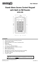
User Manual Stand-Alone Access Control Keypad with Built-in EM Reader ACSK-EM FEATURES • • • • • • • • • • • • • Timer can be set from 1 second to 60 minutes Outdoor, water resistant Built-in EM Reader; Card / Code / Combined access IP65 Rating 125KHz Frequency 1.
Disposal of Old Electrical & Electronic Equipment (Applicable in the European Union and other European countries with separate collection systems). This symbol on the product or on its packaging indicates that this product shall not be treated as household waste. Instead it shall be handed over to the applicable collection point for the recycling of electrical and electronic equipment.
INDEX FEATURES ..................................................................................................................................... 1 SAFETY WARNINGS ...................................................................................................................... 2 PACKAGE CONTENTS .................................................................................................................... 4 KEYPAD DESCRIPTION .....................................................................
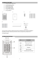
PACKAGE CONTENTS 1. 2. 3. 4. 5. 6. 7. One (1) Access Control Unit One (1) Mounting Plate One (1) Short Screw Four (4) Long Screws Four (4) Wall Anchors One (1) Torque Wrench One (1) Manual 1. 5. 2. 3. 6. 7. 4. *For any returns, please include all components listed above with original packaging in Resalable Condition. Absolutely No Returns will be accepted if any component is missing/damaged. KEYPAD DESCRIPTION No.
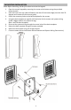
MOUNTING INSTALLATION Note: Before mounting, decide first where to mount the keypad. 1. Open the control keypad by removing the screw at the bottom using the provided torque wrench. 2. Push the front cover up a few millimeters and then lift the lower edge (no more than 20 degrees and remove the front cover gently. 2. Punch the necessary holes at the back template for the screws. 3.
SYSTEM WIRING DIAGRAM Note: White NO 1: For Electric Strike Lock Aqua NC 1: For Electric Magnetic Lock Red = DC Input: Black = White = Pink = Aqua = Brown = Orange = AC Input: ~9V ~ 18V Normally Open: N/O Electric Door Strike Lock Common - Relay Normally Close N/C Magnetic Lock Door Status Detection (See * on page 5 for DSD) Unlocking Button 1 Yellow = Unlocking Button 2 Green = GND Blue = NO 2 Purple = COM 2 Gray = NC 2 +12V ~ +24V Shielded Ground Note: The first 5 wires (b
SYSTEM WIRING CONNECTIONS Connecting to Power: Connect the Red to power positive (+). Connect the Black to power negative (-). Connecting to Locks (two options): Option1: Using a Strike Lock Connect the White to power positive (+). Connect the Pink to the Strike lock power positive (+) or the normally open (NO). Connect the Strike lock power negative (-) to the power negative (-). Option 2:Using a Magnetic Lock Connect the Aqua to power positive (+).
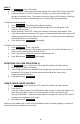
The Factory Default Programming/Admin Code is 1 2 3 4. To enter Setup Mode press Programming Code twice. (ex: 1 2 3 4 1 2 3 4) The mode LED indicator will turn yellow. To exit or quit from the Setup Mode, press # key. CHANGING PROGRAMMING/ADMIN CODE 1. 2. 3. In Setup Mode, press * key and 3. The mode indictor will flash yellow. Enter new Programming Code twice (ex: 5 6 7 8 5 6 7 8). A long beep means Programming Code was changed. The length of the Programming/Admin Code must be the same as the old one.
ADDING A MASTER CARD (ONLY FOR ZONE 1) Note: It is advisable to install the Master Card first before installing any User Cards To Add a Master Card: 1. In Setup Mode, press * key and 7. The mode LED indicator will flash green indicating there is no master card. If the mode LED indicator turns red, a Master Card is already stored. To clean up and remove, press * key twice. 2. Swipe Master Card. A long beep means master card was stored. 3. Press # key to exit Setup Mode.
ZONE 2: 1. In Setup Mode, press * key and 4. 2. Input a 2-digit number from 00-99 data storage unit. Yellow LED indicator will flash. 3. At the same time, if red LED indicator is flashing, this means the number data storage unit existed. Press * key twice to clean up. If green LED indicator is flashing, this means the number data storage unit can add card(s) and password(s). To add cards and passwords: 1. Enter Setup Mode. The yellow LED indicator will flash. 2.
REMOVING ALL USER & CODES 1. 2. 3. In Setup Mode, press * key and 8. The mode LED indicator will flash yellow. Press 8 twice. A long beep means all users and their codes were removed (except for Programming/Admin Code). Press # key to exit Setup Mode. CHANGING THE UNLOCK DELAY TIME ZONE 1: 1. In Setup Mode, press * key and 1. The mode LED indicator will flash yellow. 2. Enter unlocking delay time from 00-99 (ex: 10 means ten seconds delay time before it locks).
DOOR BELL To turn on: 1. In Setup Mode, press * key and 2. The mode LED indicator will flash yellow. 2. Press 0 and 2. A long beep will sound and the mode LED indicator will turn yellow to indicate that door bell was turned on. 3. Press # key to exit Setup Mode. To turn off: 1. In Setup Mode, press * key and 2. The mode LED indicator will flash yellow. 2. Press 0 and 1. A long beep will sound and the mode LED indicator will turn yellow to indicate that door bell was turned off. 3.
SPECIFICATIONS Model Capacity EM Reader Frequency Card Effective Distance Power Consumption DC Input AC input Current Unlock Delay Time IP Rating Operating Temperature Humidity Dimension ACSK-EM 1000 passwords & card holders (Zone 1) 10 passwords or card holders (Zone 2) 125 KHz 1.97 inch / 5 cm 12V~15V DC, 150mA +12V ~ +24V ~9V ~ 18V < 80 mA Standby / < 110 mA Working 0~99 sec IP65 -20°C ~ 50°C RH < 95% 3 (W) x 4.57 (H) x 0.87 (D) inches 7.2 (W) x 11.
OTHER RELATED PRODUCT OPTIONS A. Buzzer • Can be programmed 1~10 sec, recommend 5 sec. • 5V~14V DC Buzzer Connection: 1. Connect the buzzer positive (+) to lock (magnetic or strike) positive (+) 2. Connect the buzzer negative (-) to power negative (-) B-1. 2-CH Wireless RF Receiver & Remote + RF Receiver B-2. OR Single Button Remote 2-button Remote 2-CH Wireless RF Receiver & Desktop RF Transmitter + RF Receiver C.