
Installation Guide

21
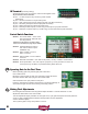
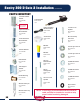
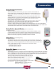
J2 Terminal (AccessoryWiring)
AccessorieswiretotheJ2connector.Insertwireandtightenscrew.
J2 pin functions are as follows:
J2pin1-+12VDCoutputforanyaccessorypowerneeded
(80mamax).
J2pin2-Groundconnectionforanyaccessoryitem.
J2pin3-Open/Exitsensorinputforopeningthegateonly(N/Oconnection)
J2pin4-Secondaryentrapmentdeviceinput(N/Oconnection).
J2pin5-SafetyReversinginput(PhotoEyeN/Oinput)
J2pin6-PhotoEyePoweroutput(+12VDConly)connectphotoeyepowerleadhere.
J2pin7-SolenoidLockPoweroutput(+12VDConly)connectsolenoidlockpowerleadhere.
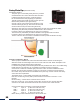
Control Switch Functions
Switch 1 Autocloseenable–Turnsonthe
autoclosefeature.Gatewillclose
fromanyposition.
DO NOT turn this feature on unless safety
devices are installed (see page 29) for details.
Switch 2 Operatingdirectionreverse–
Turn“ON”forPushtoOpen
installation only.
Switch 3 Gate1enable–Turnson
Gate1connector
Switch 4 Gate2enable–TurnsonGate2
connector
Switch 5 SolenoidLockEnable–Turn“ON”iflockpower(+12vdc)iswiredtocontrolboard.
Switch 6 PhotoEyeEnable–Turn“ON”ifphotoeyepower(+12vdc)iswiredtoJ2.6.Donot
connectphotoeyetobatteryorprematurebatteryfailurewilloccur.
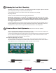
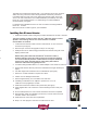
Operating Gate for the First Time
Beforeoperatinggateverifythatthegatepathisclearand
freeofobstructions.
Beawaretostopthegateincaseofanemergencysimplydisconnect
thelinearactuatorcable8pinplugfromthecontrolboard.
Gateshouldbeintheopenpositionatthispoint.
Pressthe“Open/CloseCommand”pushbutton.Thegateshouldbeginto
close.Allowthegatetotraveltothefactorypresetstopposition.
Making Final Adjustments
OncethegatehastraveledtothestoppositionadjusttheGate1“ExtendLimitMoreorLess”
adjustmentdiallocatedonthecontrolboard.
Turntheadjustmentslightlyclockwisetoclosegatemore,cyclegateandrepeatuntilclosepositionis
correct.Ifgateisadjustedpastthedesiredclosedpositionturntheadjustment
counterclockwiseslightly.
Thencyclethegatetoverifyclosepositioniscorrect.
20
21
J2 Terminal