
Data Sheet
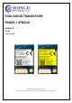
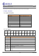
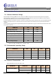
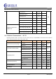
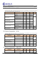
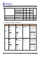
Table Of Contents
- 1. Revision History
- 2. Scope
- 3. Product Information
- 4. Introduction
- 5. Electrical Specifications
- 5-1. Absolute Maximum Ratings
- 5-2. Recommended operating Range
- 5-3. Electrical Characteristics – DC
- 5-4. Electrical Characteristics – RF TX
- 5-5. Electrical Characteristics – RF RX
- 5-6. Electrical Characteristics – RF PLL
- 5-7. Electrical Characteristics – Audio C/CS
- 5-8. AV5100 Rate Converter Characteristics
- 5-9. I2S Communication Interface Timing
- 5-10. I2C Slave Communication Interface Timing
- 6. I/O Connector Pin Description
- 7. Mechanical Specifications
- 7-1. Module dimension
- 7-2. Antenna dimension
- 8. Label Specification
- 9. Certificate Statement

PBA RF Module ATM210
5GHz
Wireless Audio Transceiver
REV: 00
Continuous TX 110
mA
Linked status for TX 49
Searching for TX 46
Continuous RX 110
Linked status for RX 93
Searching for RX 93
CMOS I/O Logic Levels –
VDDIO 3.3V
Input Voltage Logic Low, VIL
0.6
V
Input Voltage Logic High, VIH
VDDIO -
0.6V
Output Voltage Logic Low, VOL
0.3
Output Voltage Logic High, VOH
VDDIO -
0.3V
5-4. Electrical Characteristics – RF TX
Operating Conditions: VDD = 4.5 to 5.5V, TA = 0°C to +60 °C, RF Freq = 5725-5825MHz, measured to the RF conducted
2 ports. Typical specifications at TA = 25°C, VDD = 5.0V
PARAMETER CONDITION MIN TYP MAX UNIT
RF Channel Frequency Range
Low band 5150 5250
MHz
High band 5725 5825
Channel Bandwidth [OBW]
SSC (Single Sub-Carrier) 2
MHz
DSC (Dual Sub-Carrier) 4
TX Output power
SSC / Low band 5 dBm
DSC / Low band 4
SSC / High band 7 dBm
DSC / High band 6
TX Spurious(harmonic)
2nd -55 dBm
3rd -55 dBm
RF I/O Impedance ANT0, ANT1 50 ohm
LO leakage -20 dBc
8 /20
JUN 10,2019