NimbeLink-EVK User Manual Application Note SEQUANS Communications Les Portes de la Défense – Hall A 15-55 Boulevard Charles de Gaulle 92700 Colombes - France Phone. +33.1.70.72.16.00 Fax. +33.1.70.72.16.09 www.sequans.com contact@sequans.
Legal Notices Copyright© 2017, SEQUANS Communications All information contained herein and disclosed by this document is confidential and the proprietary property of SEQUANS Communications and all rights therein are expressly reserved. Acceptance of this material signifies agreement by the recipient that the information contained in this document is confidential and that it will be used solely for the purposes set forth herein.
Table of Contents Legal Notices ................................................................................................................................................ 2 Document Revision History ........................................................................................................................... 2 Referenced Documents ................................................................................................................................ 2 Table of Contents ...........
Regulatory Information USA Changes or modifications not expressly approved by the party responsible for compliance could void the user’s authority to operate the equipment. This device complies with part 15 of the FCC Rules. Operation is subject to the following two conditions: (1) This device may not cause harmful interference, and (2) this device must accept any interference received, including interference that may cause undesired operation.
—Consult the dealer or an experienced radio/TV technician for help. Considerations for the integrator Information on test modes and additional testing requirements The module has been evaluated in mobile stand-alone conditions.
1. Introduction This document provides an overview of the NimbeLink test kit, its basic installation procedures and a quick startup reference. 2. Test Kit Presentation 2.1. Test Kit Contents Out of the box, the Test Kit is delivered with Test Boards: Cellular Modem Development Kit (1) and Nimbelink Skywire® cat-M1 modem (2) based on Sequans GM01Q/NB01Q module 5V Power Supply (3) One antenna Taoglass (4) One USB-MiniUSB cable (5) Note: cat-M1 SIM card is NOT delivered as part of the Test Kit. 2.
You can access all the above optional Software tools through your contact at Sequans 2.3. Hardware setup Carefully snap out the 3FF SIM card size from the SIM card carrier, and insert it into your Skywire modem.
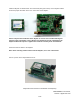
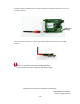
Install the Skywire as shown below. The small circle (with green arrow) on the Skywire modem shows the proper orientation of the U.FL connectors on the Skywire: Please verify that the installation of the Skywire is correct. If it is installed 180 degrees from the proper orientation, or if the Skywire is installed one pin off, it will damage the Skywire modem when power is applied. This voids the warranty of the evaluation kit. Attach the antenna cables to the Skywire.
Install the antenna to SMA connector J18 by screwing on the antenna. Make note not to crossthread the antenna: USB Port A Bend the antenna connector so it is pointing vertically. Below is a side view of the installed antenna. Note : The board is not powered through USB cable.
3. Getting Started 3.1. Board Preparation Connect the Antenna or your SMA RF Cable to the board LTE RF Connector Insert your 3FF SIM Card in the SIM slot. Plug the mini-USB cable from your PC to the board USB Port A 3.2. Drivers installation When you plug the USB connector for the first time in your PC, you need to wait for about one minute, the time to allow the drivers to be auto-installed on windows. The USB is used to power the board.
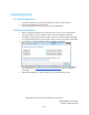
3.3. Verifying your installation After completing the drivers installation, whenever you plug the USB cable you should be able to see the following, under Windows Control Panel, Device Manager. Indeed, port enumeration can be different on your PC from the given example, depending on your local settings (example COM23, COM24…) 3.4.
3.5. Configuring and Verifying installed COM ports After COM drivers are installed, open the Windows device manager, expand Ports (COM&LPT) label and click on each one of the USB Serial Port (COMx), tab Port Settings and enter the appropriate values as described in the COM ports overview Table. 4. Using the Test Kit 4.1.
Once the correct setting is done, you should be able to start sending AT Commands and receiving their corresponding output. You can start with ATE1 to enable the echo for the current session AT Command Window Note : Upon request, your contact at Sequans can deliver you the latest version of the AT Command Reference Manual, which describe the complete list of AT commands supported by GM01Q/NB01Q Module firmware.
4.2. Console Terminal Connecting a Serial terminal to the COM port mapped on UART 2 of the Test Kit, will allow you to access to the Test Kit Console. The Console is a maintenance window, not necessary for regular operations, however it is useful to have it during maintenance phases, such Firmware upgrade or to observe the boot messages after hitting the reset button. Console Window 4.3.
o o o From the Terminal, enter : AT+CEREG=1. This command will allow getting notification every time there is a change of the network registration status From the Terminal, enter : AT+CFUN=1 Response will be OK Followed by +CEREG= o =0 : Modem is not registered and is not currently searching an operator to register to.
4.4. Checking the Signal Strength When your Kit is connected to a network, you can check the signal strength and characteristics through the following AT Command o AT+CSQ o Response will be +CSQ:, where represents the signal strength at the antenna and is the bit error rate in %.
4.5.1. Sqncom2ppp installation procedure Ask your contact at Sequans to deliver you the latest SW version of com2ppp Example com2ppp_setup_1.1-6.exe Run this application You will be guided through the following windows At this stage, SqnCom2PPP is installed on your PC 4.5.2.
From this location you can run the sqncom2ppp program. usage: sqncom2ppp [-h] {list,create,connect,disconnect,remove}. commands: list list all COM ports available. create configure COM port. connect configure COM port and establish connection. disconnect find establish PPP connection and terminate it. remove destroy PPP interface. optional arguments: -h, --help show this help message and exit.
In the Modem tab, set the correct Baudrade as indicated in the COM ports overview Table At this stage, you must reboot your computer, in order to take those settings into account. 4.5.3.
Typically in the previous example, we decided to use the same COM port for the AT command terminal and for the PPP application. For instance, omitting to disconnect the terminal will block the PPP process from succeeding. If this step succeeds, you should see the PPP connection among other existing connections, through ipconfig command and you should be able to use it. As long as you do not remove this PPP connection, you should be able to use it on this PC every time you connect the Test Kit.
5. Firmware Upgrade 5.1. Firmware Upgrade Introduction The Test Kit you receive is normally loaded with up to date Software and it is ready to work. However, your support at Sequans may ask you to upgrade the default software for some reasons at any time. To upgrade your kit you need to get from Sequans o The Sequans Firmware Upgrade Tool sfu_1.1-xxx o The SFU User Manual Monarch_SFU_UserGuide-RevX.pdf The new Firmware to upload on the Test Kit, it is a file with the .
6. DM Tool 6.1. DM Tool Introduction Most of the operations on the Modem can be run through AT Commands. However, DM Tool can allow you performing deep Monitoring and Debugging your Test sessions When you are invited to Use DM tool, you need to have access to the following deliverables from your Sequans support : o DM Tool Installation Program (sqn4gdm_setup_1.x-xxx.exe) Basic DM documentations are embedded in the tool itself, through the help Menu o TroubleShooting for DM Document 6.2.
6.3. DM Tool Configuration Read the TroubleShooting for DM Manual to become familiar with the DM tool Start DM Tool Application on the PC Open File -> Preferences on the Connections tab o Check the Enable UART box o Enter the COM port associated to UART 0.
Annex The NL-M1DK-ES has the capability to connect to your workstation via a USB-Serial connection, or to different microcontroller platforms. Your NL-M1DK-ES is setup from the factory for the USBSerial connection.