
User Manual

Installing the PIR
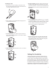
Remove the cover by inserting a screwdriver into
the slot at the bottom of the sensor. Push inward on
cover latch and remove the cover.
Push outward on circuit board latch and gently lift
circuit board and remove.
1
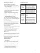
Corner mounting: Use a drill to open at least two
holes at base side depressions. Use screws to mount
on wall or in corner.
Wall mounting: Knock out hole covers. Use screws
to mount on wall
1.
2.
3.
4.
Bracket mounting (optional): Remove the knock-out
to open a hole in the center of the square recess at the
rear of the sensor base. Use screws to mount bracket in
desired location. Use screw to mount sensor base onto
the bracket.
Set the alignment post to position “0” or “1” to select
a mounting height of 7.5 ft (“0”) or 9.8 ft (“1”) above
the floor. The alignment post shifts the sensor’s field-
of-view so that it is not necessary to tilt down the
sensor when installing in a higher position.
Replace the circuit board by placing the left edge
into the mounting slots in left side of sensor base.
On right side, gently press circuit board into place
until latch snaps over circuit board.
Setting the Sensitivity
Jumper J2 determines the sensitivity mode of the sen-
sor, either standard or high sensitivity. Place the jumper
on pins 1 and 2 to select high sensitivity (pulse count 2).
Place the jumper on pin 1 with the other end hanging over
the end to select standard sensitivity (pulse count 3). Use
the standard setting for wide-angle coverage and ordinary
applications. Use high sensitivity if aggressive detection is
required. Refer to Figure 1 for location of the jumpers.
5.
6.
7.
2