
User Manual

Enrolling the Sensor
To enroll the PIR into system memory:
Enter program mode (NEXT + NEXT + NEXT +
<Prog> + Installer PIN)
The keypad will display “Devices Available.” Select
<Learn>. The display shows “Auto Enroll On.”
To enroll the PIR, remove the sensor cover.
Upon enrollment, the keypad emits one beep and
the display shows the zone number and sensor ID.
Replace the sensor cover.
Continue enrolling additional sensors if desired.
When finished, press <Done> to exit.
The following default values are applied to PIR
transmitters as they are enrolled.
Initiating Group: Interior Delayed
Response Group: Intrusion Alarm
Note: These values can be modified at option “Zone
Config” in the “ST - Zones” system programming menu.
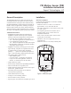
LED (Test) Mode
Place the sensor in LED mode to determine the cover-
age pattern of the sensor. The edge of the coverage
area is determined by an LED indication. The LED
is enabled by a three-pin jumper labeled J1. Refer to
Figure 1 for location of the jumper.
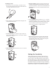
To initiate LED mode:
Remove the sensor cover and place jumper J1 on the
right two pins (Labeled “LED”).
Walk across the coverage pattern to determine the
coverage area, indicated by LED activation.
Move the jumper back to the left two pins.
Walk Test
The system contains a walk test that allows you to acti-
vate the PIR and verify wireless operation. No motion
may exist in front of detector for at least 3 minutes
prior to the walk test. Alternatively, enable LED mode
to disable the 3 minute time-out. Disable LED mode
when done to preserve battery.
To initiate a walk test:
Press NEXT + NEXT and the keypad will display
“Log Test Reset.”
Select <Test> and enter the installer or user PIN.
The display will show “Walk Comm.”
Select <Walk> and the display shows “Walk Test Active.”
Trip the PIR and the keypad responds with a tone.
The signal strength will be shown on the LCD as 1-
10. A higher value indicates a stronger signal level. A
minimum level of five is recommended.
Exit walk test mode by selecting <Done>.
1.
2.
3.
4.
5.
6.
•
•
1.
2.
3.
1.
2.
3.
4.
5.
6.
Troubleshooting
Problem Actio n
The system
indicates a
sensor trouble
for a wireless
sensor.
A trouble is caused when the sensor
tamper is activated — i.e. the sensor
cover is off, not secured, or the sensor
is not mounted properly. Secure sensor
cover and trip sensor to clear the trouble.
•
The system
indicates a
sensor low
baery.
Check that LED mode is disabled.
Replace the sensor’s battery. Trip the
sensor after replacing the battery.
Tripping allows the system to receive
a signal with the new battery data.
•
The sensor
won’t enroll into
system memory.
The sensor may already be enrolled.
Perform a walk test to verify that the
sensor is not already enrolled into the
system.
•
The panel does
not respond to
wireless sensors.
Verify that the EXT is enrolled. This
can be done by checking option “EXT
Module” (60401) in the “ST - Modules”
menu in programming. If this option is 0,
the EXT is not recognized by the system.
Bring the wireless sensors closer to the
EXT and test again. If signals are properly
received, the issue may be related to
environmental noise or interference.
•
•
3