Wireless P/T Network Camera User’s Guide
Table of Contents CHAPTER 1 INTRODUCTION.............................................................................................. 1 Overview ............................................................................................................................ 1 Physical Details - Network Camera ................................................................................. 4 Package Contents ........................................................................................................
Camera Setup .................................................................................................................. 65 Main Screen ..................................................................................................................... 69 Recording Video .............................................................................................................. 71 CHAPTER 7 TROUBLESHOOTING ..................................................................................
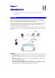
Chapter 1 Introduction 1 This Chapter provides details of the Network Camera's features, components and capabilities. Overview The Network Camera has an Integrated Microcomputer and a high quality CMOS digitalImage-Sensor, enabling it to display high quality live streaming video over your wired LAN, the Internet, and for the Network Camera, an 802.11N Wireless LAN. Using enhanced H.264 technologies, the Network Camera is able to stream high quality video and audio directly to your PC.
Suitable for Home, Business or Public Facilities. Whether for Home, Business or Public Facility surveillance, or just for entertainment and fun, the Network Camera has the features you need. Multi-Protocol Support. Supporting TCP/IP networking, SMTP (E-mail), HTTP and other Internet related protocols, the Network Camera can be easily integrated into your existing network. Easy Configuration. A Windows-based Wizard is provided for initial setup.
Wireless Features (Wireless Model Only) Standards Compliant. The Network Camera complies with the IEEE802.11N (DSSS) specifications for Wireless LANs. Supports both 802.11b and 802.11N Standards. The Network Camera supports both 802.11b and 802.11N standards. Speeds to 54Mbps. All speeds up to the 802.11N maximum of 54Mbps are supported. Wired and Wireless Network Support. The Network Camera supports either wired or wireless transmission. WEP Support.
Physical Details - Network Camera Front - Network Camera Lens No physical adjustment is required or possible for the lens, but you should ensure that the lens cover remain clean. The image quality is degraded if the lens cover is dirty or smudged. Microphone The built-in microphone is mounted on the front. Power LED (Green) On - Power on. Off - No power. Blinking - The Power LED will blink during start up. This will take 15 to 20 seconds. Active LED (Green) Off - Camera is not capturing video.
"ready" mode. WPS PBC Mode (Wireless Model Only). For the Network Camera, when pressed and released (less then 3 seconds), the Network Camera will be in the WPS PBC mode (Auto link mode). WPS Pin Code Mode (Wireless Model Only). For the Network Camera, when pressed and held for over 3 seconds, the Network Camera will be in the WPS Pin Code mode. Reset to manufacturer default value and reboot. When pressed and held over 10 seconds, the settings of Network Camera will be set to their default values.
Chapter 2 Basic Setup 2 This Chapter provides details of installing and configuring the Network Camera. System Requirements To use the wired LAN interface, a standard 10/100BaseT hub or switch and network cable is required. To use the Wireless interface, other Wireless devices must be compliant with the IEEE802.11b or IEEE802.11N specifications. All Wireless stations must use compatible settings.
Installation - Network Camera 1. Assemble the Camera Screw the supplied antenna to the mounting point on the rear. Attach the Camera Mount to the camera. 2. Connect the LAN Cable Connect the Network Camera to a 10/100BaseT hub or switch, using a standard LAN cable. For the Wireless Network Camera, plugging in the LAN cable will disable the Wireless interface. Only 1 interface can be active at any time. The LAN cable should only be connected or disconnected when the camera is powered OFF.
Setup using the Windows Wizard Initial setup should be performed using the supplied Windows-based setup Wizard. This program can locate the Network Camera even if its IP address is invalid for your network. You can then configure the Network Camera with appropriate TCP/IP settings for your LAN. Subsequent administration can be performed with your Web browser, as explained in Chapter 5 - Web-based Management. Setup Procedure 1. Insert the supplied CD-ROM into your drive.
Select the desired Camera from the list on the left. The current settings for the selected Camera will be displayed in the table on the right. Click Next to continue. 3. You will be prompted to enter the Administrator Name and Administrator Password, as shown below. If using the default values, enter administrator for the name, and leave the password blank. Otherwise, enter the Administrator Name and Administrator Password set on the Maintenance screen. Figure 4: Password Dialog 4.
Figure 6: Fixed or Dynamic IP Selection Fixed IP Address is recommended, and can always be used. Dynamic IP Address can only be used if your LAN has a DCHP Server. Click Next to continue. 6. If you chose Fixed IP Address, the following TCP/IP Settings screen will be displayed. Figure 7: TCP/IP Settings Enter an unused IP Address from within the address range used on your LAN. The Subnet Mask and Default Gateway fields must match the values used by PCs on your LAN.
7. The next screen, shown below, displays all details of the Network Camera. Click Next if the settings are correct Click Back to modify any incorrect values. Figure 8: Save Settings 8. Click OK to confirm that you want to save the new settings. If you want to cancel your changes, click Cancel. Figure 9: Confirm Screen 9. After clicking OK, you will see the screen below.
Figure 10: Final Screen Clicking the Install Utility button will install the Viewing/Recording utility described in Chapter 6 - Windows Viewing/Recording Utility. 10. Click Exit to end the Wizard. Setup is now complete.
Chapter 3 Viewing Live Video 3 This Chapter provides basic information about viewing live video. Overview After finishing setup via the Windows-based Wizard, all LAN users can view live video using Internet Explorer on Windows. This Chapter has details of viewing live video using Internet Explorer.
Figure 11: Home Screen 5. Click View Video. 6. If the Administrator has restricted access to known users, you will then be prompted for a username and password. Enter the name and password assigned to you by the Network Camera administrator. 7. The first time you connect to the camera, you will be prompted to install an ActiveX component (OCX or CAB file), as in the example below. You must install this ActiveX component (OCX or CAB file) in order to view the Video stream in Internet Explorer.
Connecting to a Camera via the Internet You can NOT connect to a camera via the Internet unless the camera Administrator has configured both the camera and the Internet Gateway/Router used by the camera. See Making Video available from the Internet in Chapter 4 - Advanced Viewing Setup for details of the required configuration. Also, you need a broadband Internet connection to view video effectively. Dial-up connections are NOT supported.
4. When you connect, the following screen will be displayed. Figure 13: Home Screen 5. Click View Video. 6. If the Administrator has restricted access to known users, you will then be prompted for a username and password. Enter the name and password assigned to you by the Network Camera administrator. 7. The first time you connect to the camera, you will be prompted to install an ActiveX component (OCX or CAB file), as in the example below.
Viewing Live Video After installing the ActiveX component, you will be able to view the live video stream in its own window, as shown below. Figure 15: View Video Screen There are a number of options available on this screen, accessed by select list, button or icon. See the table below for details. General Options These options are always available, regardless of the type of camera you are connected to. Camera Patrol. Move through the Preset positions in the sequence defined by the Camera Administrator.
Mirror. Click this to have the image swapped left-to-right. Audio On. This icon is displayed if audio is On. Click on the icon to turn audio Off. Volume. If audio is enabled, use this slider to adjust the volume. Setup. Select the desired setup format from the drop-down list. Preset Points. Select the desired Preset points. Move Control. Use this to move the camera to the desired position. There may a short delay after clicking the desired icon. You should wait a couple of seconds rather than click again.
Chapter 4 Advanced Viewing Setup 4 This Chapter provides information about the optional settings and features for viewing video via the Network Camera. This Chapter is for the Camera Administrator only.
11. Make the required adjustments, as explained below, and save your changes. MPEG-4 Settings Resolution Video Quality Control Max. Frame Rate Select the desired video resolution format. The default resolution is set to 320*240. Constant Bit Rate: Select the desired bit rate. The default is set to 1.2 Mbps. Fixed Quality: Select the desired option. The default fix quality is set to Normal. Select the desired Maximum bandwidth for the video stream.
Sharpness Select the desired option for the sharpness. You can select a Sharpness value between -3 and 3. Options Microphone Enable audio by checking this checkbox. Using Audio will increase the bandwidth requirements slightly. Audio Type Select the desired audio type. Speaker Enable speaker sound by checking this checkbox. Time Stamp If enabled, the current time will be displayed on the Video image.
Viewing the live Video on your cell phone The live streaming of the Network Camera can even be viewed from a compatible cell phone, so you can keep an eye on things almost everywhere you go, with no PC required! It’s just as easy as following the required steps. To Adjust the Mobile Settings 1. Connect to the Web-based interface of the Network Camera. (See Chapter 5 - Web-based Management for details.) 2. Select Administration, then Video & Audio. You will see a screen like the example below.
Connecting Cell Phone to the Network Camera A number of different mobile handsets are compatible with the Network Camera, among them RIM's BlackBerry, Palm's Palm OS Treo models, Motorola's RAZR, Nokia's N72 and Sony Ericsson's W810i, more, on Sprint, Cingular, T-Mobile and Verizon's wireless networks. 1. Start IE 2. Select Add Bookmark 3. Click Edit 4. Enter desired value for Subject or leave it blank 5. Enter the camera’s IP 6.
Controlling User Access to the Video Stream By default, anyone can connect to the Network Camera and view live Video at any time. If desired, you can limit access to scheduled times, and also restrict access to known users. To Control User Access to Live Video: 1. Connect to the Web-based interface of the Network Camera. (See Chapter 5 - Web-based Management for details.) 2. Select Administration, then Video Access. 3. Set the desired options for Access.
Making Video available from the Internet If your LAN is connected to the Internet, typically by a Broadband Gateway/Router and Broadband modem, you can make the Network Camera available via the Internet. You will need to configure your Router or Gateway to allow connections from the Internet to the camera. Router/Gateway Setup Your Router or Gateway must be configured to pass incoming TCP (HTTP) connections (from Internet Viewers) to the Network Camera.
Network Camera Setup The Network Camera configuration does NOT have be changed, unless: You wish to change the port number from the default value (1024). You wish to use the DDNS (Dynamic DNS) feature of the Network Camera. HTTP Port Configuration Normally, HTTP (Web) connections use port 80. Since the Network Camera uses HTTP, but port 80 is likely to be used by a Web Server, you can use a different port for the Network Camera. This port is called the Secondary Port.
Figure 21: DDNS Screen 3. Operation is then automatic: The Network Camera will automatically contact the DDNS server whenever it detects that the Internet IP address has changed, and inform the DDNS server of the new IP address. Internet users can then connect to the camera using the Domain Name allocated by the DDNS service provider. Viewing Live Video via the Internet Clients (viewers) will also need a broadband connection; dial-up connections are NOT recommended.
Where the Router/Gateway's Domain name is mycamera.dyndns.tv and the "Secondary Port" number on the Network Camera is 1024. Viewing Live Video with the Viewing/Recording Utility If using the Windows Viewing/Recording Utility, the details of the Network Camera must be entered on the Camera Setup screen. Figure 22: Add Camera from Internet See Chapter 6 - Windows Monitor/Playback/IP Recorder Utility for full details on using the Windows Viewing/Recording utility.
Motion Detection Alerts The Motion Detection feature can generate an Alert when motion is detected. The Network Camera will compare consecutive frames to detect changes caused by the movement of large objects. But the motion detector can also be triggered by: Sudden changes in the level of available light Movement of the camera itself. Try to avoid these situations. The motion detection feature works best in locations where there is good steady illumination, and the camera is mounted securely.
Enter details of the SMTP Server used to send the E-mail. If the Motion Detection feature is enabled, but E-Mail is not enabled, then the only action when motion is detected is to log this event in the system log.
Chapter 5 Web-based Management 5 This Chapter provides Setup details of the Network Camera’s Web-based Interface. This Chapter is for the Camera Administrator only. Introduction The Network Camera can be configured using your Web Browser. The Network Camera must have an IP address which is compatible with your PC. The recommended method to ensure this is to use the supplied Windows-based Wizard, as described in Chapter 2 - Basic Setup.
Welcome Screen When you connect, the following screen will be displayed. Figure 24: Welcome Screen The menu options available from this screen are: View Video - View live Video using your Web Browser. See Chapter 3 - Viewing Live Video for details. Administration - Access the Administration menu.
Administration Menu Clicking on Administration on the menu provides access to all the settings for the Network Camera.
System Screen After clicking Administration on the main menu, or selecting System on the Administration menu, you will see a screen like the example below. Figure 25: System Screen Data - System Screen System Settings Device ID This displays the name for the Network Camera. Camera Name Enter the desired name for the Network Camera. Description This field is used for entering a description, such as the location of the Network Camera.
Current Date & Time Time Zone This displays the current date and time on the camera. If it's not correct, click the Change button to modify the date/time settings. This button will open a sub-screen where you have 2 options: Set the camera's date and time to match your PC. Enter the correct date and time. Choose the Time Zone for your location from the drop-down list. If your location is currently using Daylight Saving, enable the Adjust for daylight saving checkbox.
Network Screen This screen is displayed when the Network menu option is clicked. Figure 26: Network Screen Data - Network Screen Network Obtain an IP Address Automatically If selected, the Network Camera will obtain its IP address and related information from a DHCP Server. Only select this option if your LAN has a DHCP Server. Use the following IP Address If selected, you must assign the following data to the Network Camera.
Secondary Port This sets the port number for HTTP (Web) connections to the Camera, whether for administration or viewing video. If enabled, you can connect using either port 80 or the Secondary port. You must enter the Secondary port number (between 1024 to 65535) in the field provided. Note that when using a port number which is not 80, you must specify the port number in the URL. For example, if the Camera's IP address was 192.168.1.
Wireless Screen (Wireless Model Only) This screen is displayed when the Wireless menu option is clicked. Figure 27: Wireless Screen Data - Wireless Screen Wireless Network WSC PIN Code It displays the WSC PIN code number for the camera. Network Type This determines the type of wireless communication used by the Network Camera. If you have an Access Point, select Infrastructure. Otherwise, select Ad-hoc. SSID This must match the value used by other devices on your wireless LAN.
Security Security System Select the desired option, and then enter the settings for the selected method: Disabled - No security is used. Anyone using the correct SSID can connect to your network. WEP - The 802.11b standard. Data is encrypted before transmission, but the encryption system is not very strong. WPA/WPA2 Personal - Like WEP, data is encrypted before transmission. WPA is more secure than WEP, and should be used if possible.
DDNS Screen Many Internet connections use a "Dynamic IP address", where the Internet IP address is allocated whenever the Internet connection is established. This means that other Internet users don't know the IP address, so can't establish a connection. DDNS is designed to solve this problem, as follows: You must register for the DDNS service with a DDNS service provider. The DDNS Service provider will allocate a Domain Name to you upon request.
Web Site Button Click this button to open a new window and connect to the Web site for the selected DDNS service provider. Domain (Host) Name Enter the Domain Name (Host Name) allocated to you by the DDNS Server provider. Account/E-Mail Enter the login name for the DDNS account. Password/Key Enter the password for the DDNS account. Check WAN IP Address Set the schedule for checking if the Internet IP address has changed. If the IP address has changed, the DDNS Server will be notified.
Video & Audio Screen This screen is displayed when the Video & Audio option is clicked. Figure 29: Video & Audio Screen Data - Video & Audion Screen MPEG-4 Settings Resolution Video Quality Control Select the desired video resolution format. The default resolution is set to 320*240. Constant Bit Rate: Select the desired bit rate. The default is set to 1.2 Mbps. Fixed Quality: Select the desired option. The default fix quality is set to Normal.
Max. Frame Rate Select the desired Maximum bandwidth for the video stream. Note that you can specify EITHER the Bandwidth OR the Frame Rate, not both. If the Bandwidth is defined, the frame rate will be adjusted as necessary to achieve the specified frame rate. The default value for bandwidth is Unlimited, which allows you to specify the desired frame rate. MJPEG Settings Resolution Select the desired video resolution format. The default resolution is set to 320*240.
Text Display Enable this setting if you want text to be displayed on the Video image, and enter the desired text - up to 20 characters. This feature is often used to identify each camera when multiple cameras are installed.
Video Access Screen This screen is displayed when the Video Access option on the Video & Audio menu is clicked. Figure 30: Video Access Screen Data - Video Access Screen User Access Enable Security Checking If disabled - No login required, users do not have to provide a username and password when they connect to the camera to view video. If enabled - Require login, users will be prompted for a username and password when they connect to the camera to view video.
Delete Use the Delete button to delete the selected item in the list. Add Period Day Choose the desired option for the period. Start Time Enter the start time using a 24 hr clock. End Time Enter the end time using a 24 hr clock. Add Click this button to add a new period.
User Database Screen This screen is displayed when the User Database option on the Video & Audio menu is clicked. Figure 31: User Database Screen Data - User Database Screen Existing Users User List This displays all users you have entered into the User database. If you have not entered any users, this list will be empty. Edit, Delete, Delete All Use these buttons to manage the user database. User Properties User Name Enter the name for the user here.
Pan/Tilt Screen This screen is displayed when the Pan/Tilt option on the Video & Audio menu is clicked. Figure 32: Pan/Tilt Screen Data - Pan/Tilt Screen Pan/Tilt Enable Pan/Tilt Control Enable the checkbox in order to use the Pan/Tilt function. Preset Point Position Click this button to define the preset point position.
Set Patrol Sequence Set Patrol Sequence This feature determines how the camera will move when it is set to "Rotate". You can set a number of Preset Positions; the camera will go to the first position, then move through the list of present positions until it is finished. The camera will stop at the last position in the list. To create the Preset Sequence, select the desired Preset Position in the left column, and click the "Add >>" button. Repeat until the desired sequence is complete.
Set Preset Position Screen This screen is displayed when the Preset Point Positions button on the Pan/Tilt screen is clicked. Figure 33: Preset Point Position Screen Data - Preset Point Positions Calibration Click this button to reset the calibration of Pan/Tilt area. Preset List Select the desired Preset. The screen will update with the current data for the selected Preset Position. Preset Name Enter a suitable name for the Preset Position. If no name is entered, the preset will have a number only.
Motion Detection Screen This screen is displayed when the Motion Detection option on the Event menu is clicked. . Figure 34: Motion Detection Screen Data - Motion Detection Screen Motion Detection Set Detection Areas You can set the full screen or areas of the video image to be examined. Note: Motion detection can be triggered by rapid changes in lighting condition, as well as by moving objects. For this reason, it should only be used indoors. Threshold Adjust the threshold of detection for each area.
E-Mail Screen This screen is displayed when the E-Mail option on the Event menu is clicked. . Figure 35: E-Mail Screen Data - E-Mail Screen Primary/Secondary SMTP Server SMTP Server Address Enter the address of the SMTP (Simple Mail Transport Protocol) Server to be used to send E-Mail. Authentication Select the desired Authentication type for the SMTP Server. SMTP Login name Enter your login name for the SMTP Server. SMTP Password Enter your password for the SMTP Server.
E-Mail Setup E-Mail Address Enter at least one (1) E-Mail address; the 2nd and 3rd addresses are optional. The E-Mail alert will be sent to the E-Mail address or addresses specified here. Subject Enter the desired text to be shown as the "Subject" for the E-Mail when it is received. Subject can not exceed 48 alphanumeric characters.
FTP Screen This screen is displayed when the FTP option on the Event menu is clicked. Figure 36: FTP Screen Data - FTP Screen Primary/Secondary FTP FTP Server Enter the address of the FTP Server. Port Enter the Port of the FTP Server to be connected. Login name Enter your login name for the FTP Server. Password Enter your password for the FTP Server. Enable Passive Mode Check the box to enable the Passive mode feature of the FTP. File Path Name Enter the file path/name of the FTP.
HTTP Screen This screen is displayed when the HTTP option on the Event menu is clicked. Figure 37: HTTP Screen Data - HTTP Screen HTTP Notification Enable Enable this checkbox to use the HTTP Notification. URL Enter the URL of your HTTP notification server. Proxy Server Name Specify the proxy server name in the provided field if the camera needs to pass through a Proxy Server to do the HTTP notification. Port Number Enter the port number for the proxy server.
Event Trigger Screen This screen is displayed when the Event Trigger option on the Event menu is clicked. Figure 38: Event Trigger Screen Data - Event Trigger Screen Event Schedule Schedule List The Event Schedule shows all of the event types currently configured in the Network Camera, along with various information about their configuration, as listed below: Name - the descriptive event name set by the user. Effective Time Frame - shows when the event at a set time will be triggered.
Start Time Choose the desired start time using a 24 hr clock. End Time Choose the desired end time using a 24 hr clock. Trigger Event Motion Detection If enabled, movement in a motion detection window can be used to trigger events. Pan/Tilt Configuration This option is only available if your camera is fitted with a Pan/Tilt control. If available, select the desired option to resolve conflict between the Pan/Tilt and Motion Detection features.
Maintenance Screen . Figure 39: Maintenance Screen Data - Maintenance Screen Administrator Login Administrator ID Enter the name for the Administrator here. Administrator Password The password for the Administrator. Verify Password Re-enter the password for the Administrator, to ensure it is correct. Spaces, punctuation, and special characters must NOT be used in the name.
Backup & Restore Backup Configuration File Click Backup button to save the current configuration information to a text file. Restore Configuration File Click Restore button to reinitialize the camera to load the new updated software. Do this after loading the upgrade file. Clear File Name This does NOT stop the Restore process if it has started. It only clears the input for the "Restore Configuration File" field.
Status Screen . Figure 40: Status Screen Data - Status Screen System Device Name This shows the name of the Network Camera. Description This shows the description of the Network Camera, such as location. F/W version The version of the current firmware installed. Network MAC Address The current IP address of the Network Camera. IP Address The IP Address of the Network Camera. Network Mask The network mask associated with the IP address above.
Network Type This shows the Network Type currently in use (Ad-hoc or Infrastructure). SSID This displays the wireless SSID. Channel This shows the wireless channel currently used. Security The current security setting for Wireless connections. Signal Strength This shows the strength of the signal. MPEG-4/MJPEG Resolution The image size of the video stream. Video Quality This displays the image quality of the video stream. Frame Rate This displays the frame rate of the video stream.
Log Screen This screen displays a log of system activity. . Figure 41: Log Screen Data - Log Screen Log System Log This is a log of system activity. Enable Syslog Service Check the box to enable the System Log Server feature. Syslog Server Address Enter the address of the Syslog Server. Refresh Button Click this to update the data shown on screen. Clear Log Click this button to restart the log.
6 Chapter 6 Windows Monitor/Playback/IP Recorder Utility This Chapter describes how to view and record the live video stream generated by the Network Camera, using the supplied Windows utility. Overview The recommended method to view video is to use the supplied Windows Viewing/Recording utility. This utility also allows you to record the video streams, either interactively or using a schedule. Installation 1. Insert the supplied CD-ROM into your drive.
System Tray Icon When started, the program will create an icon in the Windows system tray on the taskbar, as shown below. Figure 43: System Tray Icon You can right click the icon and it will provides a menu which allows you to view program details, view the main screen, or terminate the program. Main Screen When started, a screen like the example below will be displayed. Figure 44: Main Screen If no cameras have been defined, no video will be displayed.
Camera Setup To define a camera and associate it with a Channel Number. 1. Click the Setup button on the main screen. You will see a screen like the example below. Figure 45: Camera Setup Screen 2. Select the desired Channel number in the left (No.) column. 3. There are 2 radio buttons, for LAN or Internet. The default is LAN. See the following section for details of the Internet option. The LAN panel, on the left, displays all Network Camera found on your LAN.
Port Number This will normally display "80". Only change this if requested to do so by the Network Camera Administrator. Login The camera Administrator can require that users provide a username and password before being allowed to view the live video. If the Administrator has not enabled this option, the Login fields can be left blank. Otherwise, you must enter the username and password allocated to your by Administrator.
Adding Cameras on the Internet If the Network Camera you wish to add is not on your LAN, but is available via the Internet, click the Internet button. You will see a screen like the example below. Figure 46: Add Camera from Internet To associate a camera with the current Channel: 1. Enter the Camera Data on the panel on the right. See below for details. 2. If desired, click the Test button to check that a connection and login can be performed successfully.
The camera Administrator can require that users provide a username and password before being allowed to view the live video. Login If the Camera Administrator has not enabled this option, the Login fields can be left blank. Otherwise, you must enter the username and password allocated to you by the Camera Administrator. Stream Type Select the desired video stream type. There might be either MPEG4 or Motion-JPG streaming type.
Main Screen You can view live video in the main screen. The built-in software can let you view up to 9 cameras on a single computer screen at one central location. The Icons allow you to control the cameras and video streams. Channel (Camera) Selection. Use this to select the desired Channel (Camera) by clicking on the top row. This panel also indicates the status of the camera. The first column indicates if the camera is available. Green indicates the camera is available.
Stop. This will terminate the connection to the camera, halting both the viewing and the recording (if in progress). Record. Click this to start recording the current video stream. While recording, this button will be blue. To stop recording, click the Stop button. Snapshot. Click this to take a single JPEG "snapshot" image of the current video. Zoom Camera. A digital zoom feature is available. To zoom in on a section of the window, click this icon.
Recording Video You can record Video while watching, or schedule recordings to occur when you are absent. Recordings are stored in a standard Microsoft ASF file format, and can be played using Microsoft Media Player. Before doing any recording, you should review the recording settings to ensure they are suitable for your PC. Recording Schedule To set the Recording Preferences, click the Recording Schedule tab on the Setup screen. You will see a screen like the example below.
Preferences This screen is displayed after clicking the Preferences tab on the Setup screen. If necessary, change these settings to suit your environment. Figure 48: Preferences Screen Data - Preferences Recording Paths Recording This is the Drive and Folder on your PC where recorded files will be placed. You need a drive which has large amounts (Gigabytes) of free space. Click the Browse button to select the drive and folder. Note that file names are automatically assigned, using the date and time.
Record after Trigger Event Set the time so the Utility will stop recording the certain time after the Utility detects motion in a Camera's field of view. Disk Allocation for Each Camera Recording Total Disk Space This displays the total size of the disk selected for storing recordings. Available Disk Space This displays the available space of the disk selected for storing recordings. Enable Disk space limitation Enable this if you wish to limit the disk space used by video recordings.
Using Playback To access the saved files of the Camera, click Playback button in the Main screen, then you will see the following screen. Figure 49: Playback Screen Searching Recorded Video Files Select Camera. Select the desired camera from the list. Recording Methods. Select the type of the recorded file from the drop-down list that you wish to view. Start Date/Time. The date and time the recording will be made. End Date/Time. The date and time the recording will be ended. Load other Cameras.
Print. Click this to print the current video stream. Playback Speed. To play a recorded file, select the desired speed. Audio Control. To play a recorded file, select the desired volume. Delete Video. To delete a recorded file, select the file and click this button.
Chapter 7 Troubleshooting 7 This chapter covers the most likely problems and their solutions. Overview This chapter covers some common problems that may be encountered while using the Network Camera and some possible solutions to them. If you follow the suggested steps and the Network Camera still does not function properly, contact your dealer for further advice. Problems Problem 1: I can't connect to the Network Camera with my Web Browser to configure it.
indicates that the Administrator has restricted access to specified users. Ask the Administrator for your User Name and Password. Problem 4 I can't connect to the Network Camera using a Wireless connection. Solution 4 1) If a LAN cable is connected to the LAN port, the Wireless interface is disabled. Only one interface can be active. 2) Check that your PC and the Network Camera have compatible Wireless settings. Mode (Infrastructure or Ad-hoc) must be correct. ESSID must match.
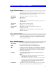
Appendix A Specifications A Network Camera Model Network Camera Dimensions 90mm (W) * 35mm (H) * 90mm (D) Operating Temperature 0 C to 40 C Storage Temperature 0 C to 40 C Network Protocols TCP/IP, DHCP, SMTP, NTP, HTTP, FTP, RTP, RTSP, UPnP (Discovery/Traversal) Network Interface 1 Ethernet 10/100BaseT (RJ45) LAN connection Wireless interface IEEE 802.11b/802.
(Example - use only shielded interface cables when connecting to computer or peripheral devices). FCC Radiation Exposure Statement This equipment has been tested and found to comply with the limits for a Class B digital device, pursuant to part 15 of the FCC rules. These limits are designed to provide reasonable protection against harmful interference in a residential installation.
Copyright Notice Many software components are covered by the GNU GPL (General Public License). Some are covered by other Licenses as listed in the table below. Details of each applicable license are contained in the following section. No Warranty THIS SOFTWARE IS PROVIDED BY THE AUTHOR AND CONTRIBUTORS '' AS IS'' AND ANY EXPRESS OR IMPLIED WARRANTIES, INCLUDING, BUT NOT LIMITED TO, THE IMPLIED WARRANTIES OF MERCHANTABILITY AND FITNESS FOR A PARTICULAR PURPOSE ARE DISCLAIMED.
thttpd.c - tiny/turbo/throttling HTTP server Copyright ?1995,1998,1999,2000,2001 by Jef Poskanzer All rights reserved. Redistribution and use in source and binary forms, with or without modification, are permitted provided that the following conditions are met: 1. Redistributions of source code must retain the above copyright notice, this list of conditions and the following disclaimer. 2.
ntp-4.1.71 license Copyright (c) David L.
cron license Copyright (c) 1989 The Regents of the University of California. All rights reserved. This code is derived from software contributed to Berkeley by Paul Vixie.
GNU General Public License GNU GENERAL PUBLIC LICENSE Version 2, June 1991 Copyright (C) 1989, 1991 Free Software Foundation, Inc. 51 Franklin St, Fifth Floor, Boston, MA 02110-1301 USA Everyone is permitted to copy and distribute verbatim copies of this license document, but changing it is not allowed. Preamble The licenses for most software are designed to take away your freedom to share and change it.
translated into another language. (Hereinafter, translation is included without limitation in the term "modification".) Each licensee is addressed as "you". Activities other than copying, distribution and modification are not covered by this License; they are outside its scope. The act of running the Program is not restricted, and the output from the Program is covered only if its contents constitute a work based on the Program (independent of having been made by running the Program).
b) Accompany it with a written offer, valid for at least three years, to give any third party, for a charge no more than your cost of physically performing source distribution, a complete machine-readable copy of the corresponding source code, to be distributed under the terms of Sections 1 and 2 above on a medium customarily used for software interchange; or, c) Accompany it with the information you received as to the offer to distribute corresponding source code.
practices. Many people have made generous contributions to the wide range of software distributed through that system in reliance on consistent application of that system; it is up to the author/donor to decide if he or she is willing to distribute software through any other system and a licensee cannot impose that choice. This section is intended to make thoroughly clear what is believed to be a consequence of the rest of this License. 8.
END OF TERMS AND CONDITIONS 88
Lesser GNU General Public License GNU LESSER GENERAL PUBLIC LICENSE Version 2.1, February 1999 Copyright (C) 1991, 1999 Free Software Foundation, Inc. 51 Franklin St, Fifth Floor, Boston, MA 02110-1301 USA Everyone is permitted to copy and distribute verbatim copies of this license document, but changing it is not allowed. [This is the first released version of the Lesser GPL. It also counts as the successor of the GNU Library Public License, version 2, hence the version number 2.1.
Finally, software patents pose a constant threat to the existence of any free program. We wish to make sure that a company cannot effectively restrict the users of a free program by obtaining a restrictive license from a patent holder. Therefore, we insist that any patent license obtained for a version of the library must be consistent with the full freedom of use specified in this license. Most GNU software, including some libraries, is covered by the ordinary GNU General Public License.
The "Library", below, refers to any such software library or work which has been distributed under these terms. A "work based on the Library" means either the Library or any derivative work under copyright law: that is to say, a work containing the Library or a portion of it, either verbatim or with modifications and/or translated straightforwardly into another language. (Hereinafter, translation is included without limitation in the term "modification".
In addition, mere aggregation of another work not based on the Library with the Library (or with a work based on the Library) on a volume of a storage or distribution medium does not bring the other work under the scope of this License. 3. You may opt to apply the terms of the ordinary GNU General Public License instead of this License to a given copy of the Library.
6. As an exception to the Sections above, you may also combine or link a "work that uses the Library" with the Library to produce a work containing portions of the Library, and distribute that work under terms of your choice, provided that the terms permit modification of the work for the customer's own use and reverse engineering for debugging such modifications.
8. You may not copy, modify, sublicense, link with, or distribute the Library except as expressly provided under this License. Any attempt otherwise to copy, modify, sublicense, link with, or distribute the Library is void, and will automatically terminate your rights under this License. However, parties who have received copies, or rights, from you under this License will not have their licenses terminated so long as such parties remain in full compliance. 9.
14. If you wish to incorporate parts of the Library into other free programs whose distribution conditions are incompatible with these, write to the author to ask for permission. For software which is copyrighted by the Free Software Foundation, write to the Free Software Foundation; we sometimes make exceptions for this. Our decision will be guided by the two goals of preserving the free status of all derivatives of our free software and of promoting the sharing and reuse of software generally.
Appendix B Streaming Video/Audio B Solution Overview Streaming video is a sequence of "moving images" that are sent in compressed form over the Internet and displayed by the viewer as they arrive. With streaming, a Web user does not have to wait to download a large file before seeing the video or hearing the sound. Instead, the media is sent in a continuous stream and is played as it arrives.