TPM541 series Cat-M1/NB Module TPM541 series EVK USER GUIDE Revision 1.4 Oct. 2020 Specifications are subject to change without notice and should not be construed as a commitment by Sercomm Corporation Copyright 2017 by Sercomm Corporation All rights reserved.
TPM541 series Frequency Bands One SKU for all, Supported Bands are configurable (B2/3/4/5/8/12/13/20/25/26/28) Only Bands 2/4/12 are enabled and available for this device; all other bands are disabled via software when sold/marketed to the USA Data Data rate: Max throughput UL/DL (23dBm): UL: 375kbps/DL: 300kbps (peak) Protocol stack: COAP*/IPV4/IPV6/MQTT*/HTTPS*/LWM2M PPP/UDP/TCP/TLS/DTLS Firmware Download Method: UART, FOTA Electrical Specification Maximum RF output power: 23 dBm (tolerance 2
TPM541 series Cat-M1/NB Module Table of contents Data ................................................................................................................................................................................... 2 Electrical Specification ........................................................................................................................................................ 2 Power Consumption .............................................................................
TPM541 series Cat-M1/NB Module 1. Introduction 1.1. Document Purpose The purpose of this document is to introduce TPM541 series EVK and to provide a design reference. EVK also enables users to make a prototype on TPM541 platform which resembles the actual target during the design and build phases of a project. It makes the design efforts of a user simple, cost-effective and fast. Various interfaces which is included on the board make the development board ideal for a wide variety of applications.
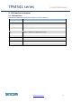
TPM541 series Cat-M1/NB Module 2. EVK functions introduce 2.1. EVK Interfaces Table 2.2 lists TPM541 series available interfaces on EVK for reference . Interface Note UART0/J3 UART1/J2 UART2/J7 USIM/J17 JP5 JP2 JP1 J19 S2 J8/J21 J6/J11 J1 AT commands UART interface, default baud rate: 115200 Console Log UART interface, default baud rate: 115200 CLI/Firmware upgrade UART interface, default baud rate: 115200 SIM card slot, supports 3FF, micro SIM card UART0 to USB/external MCU switch jump.
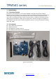
TPM541 series Cat-M1/NB Module 3. Starting with TPM541 series EVK 3.1. Hardware preparation and setup Attach the included antenna to the SMA connectorJ21 Plug-in the included DC adapter to DC Jack J1 Or each UART to USB cable. Plug-in 3FF SIM card to J17(back side of EVK) Switch on S2(Power switch) to turn on the module. There is no need to turn on S2 while using USB cable to power up EVK Module PWR1 LED will be lighted when power EVK successfully.
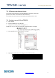
TPM541 series Cat-M1/NB Module 3.2. Software preparation and setup Prepare and install Silicon Lab CP210X UART to USB Driver, Version 6.7 (Please access Silicon Lab website to download driver.) Prepare Serial Port Terminal Tool (Putty, SecureCRT, Teraterm..etc) 3.3. Starting to access EVK and TPM541 a. Turn on EVK b. Connect UART0 to PC via USB cable. c. Setup Terminal tools, please refer figure 3.3 (COM port: com port will be enumerated on Windows device manager) d.
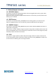
TPM541 series Cat-M1/NB Module 4. Button/Jumper introduce 4.1. RECOVERY button : This button is used to enter boot ROM mode for firmware upgrade and recovery system when device cannot boot up by some reason. Please visit Sercomm technical support website and issue a ticket when you have problem with booting up your TPM541. 4.2. RESET button : This button is connected to PMU_SHUTDOWN pin for initiating power cycle that resets the device or shutdowns device.
TPM541 series Cat-M1/NB Module 5. LED status 5.1. Module_PWR1 LED: For VCC status indication. ON: VCC is present. OFF: VCC is absent. VCC is provided by 5V to 3.3V LDO. 5.2. Module_LED1: This LED is controlled by PMU_EXT_ALARM pin, it can be used for alarming an external host. Output Conditions High Active , LS, DS Low DH0, DH1 and DH2 5.3. Module_LED2: Reserved www.sercomm.
TPM541 series Cat-M1/NB Module 6. Special hardware configuration pins 6.1. SWD(JP17): TBD 6.2. Isolation control(JP3): 3.3V to 1.8V level shift ICs(U3,U10,U11) control : H: Turn off level shift ICs L: Turn on level shift ICs Default is connected to Low. 6.3. Debug Selection(JP12): HW pin for EJTAG chain select : PD for MIPS chain. PU for ARM chain. Default setting is internal PD in TPM541. 6.4.
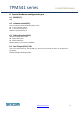
TPM541 series Cat-M1/NB Module 7. RF matching diagram example LTE_ANT port is the primary (main) antenna pin and carries TX and RX signals. Connect 50 Ohm transmission lines from this pins to the 50 Ohm Primary Antenna/Antennaconnector. Figure 7.1 shows the connection between LTE_ANT port and the antenna connectors please also follow up matching network to fine tune antenna matching. Figure 7.1 RF matching typical circuit. www.sercomm.
TPM541 series Cat-M1/NB Module 8. Firmware Upgrade Please access https://supportiot.sercomm.com/ to download and install PC Tools for local firmware upgrade. And you will find ImageBurnTool in program after finish installation. ImageBurnTool is used for local firmware upgrade via UART_2 In the mean time, please also download images that have two parts need to be installed in your PC/Laptop. RK_02_01_02_00_xx TPM540G_05.00x 8.1. Install RK firmware image 1. Please create folder “RiceKrispies” under C:\
TPM541 series Cat-M1/NB Module 4. Click Close after installing completed 5. Unzip Sercomm firmware image “TPM540G_05.00x.zip” that downloaded from Sercomm support IoT website. 6. COPY all files and replace files under folder path: C:\Program Files (x86)\Altair Semiconductor\RiceKrispies\RK_02_01_02_00_XX\Images Note : a).For 64bit windows OS, the folder path is “C:\Program Files (x86)\Altair Semiconductor\RiceKrispies\RK_02_01_02_00_XX\Images” b).For 32bit windows OS, the folder path is “C:\Program File
TPM541 series Cat-M1/NB Module Now, all the necessary firmware images are installed well in your PC/Laptop. 8.2. Environment setup Local upgrade is flashed the firmware through local UART_2 port. Please follow this instruction step by step to setup your environment for upgrade. 8.2.1. Open your UART_0 with terminal tools. a. Turn on EVK b. Connect UART_0 to PC via USB cable. c. Setup Terminal tools, please refer figure 7.2.1. COM port: com port will be enumerated on Windows device manager d.
TPM541 series b. Cat-M1/NB Module After power to the module. User need to “Hit any key to stop autoboot” within 10s and you will see “#” prompt that means TPM541 is successfully into U-BOOT mode. Before starting flashing image, User need to disconnect the connection between UART2 and terminal tool. 8.3. Firmware upgrade with ImageBurnTool This chapter is introduced how to setup configuration of ImageBurnTool.
TPM541 series b. Cat-M1/NB Module If you already have installed RK image well, ImageBurnTool will detect latest RK image automatically in “Version” c. Please go through all steps of chapter 7.1 again if tool cannot detect firmware version. Or you can select the version manually. Then you need to select images that need to be upgraded. Here we recommend to upgrade all parts EXCEPT “Configuration FS”.
TPM541 series Cat-M1/NB Module Warning, DO NOT select Configuration FS, in case the calibration data will be erased after firmware upgrade. 8.3.2. Setup “Burn Options” Currently TPM541 series only supports Firmware upgrade through UART, USB hasn’t supported yet. Please select COM NO. With UART_2 and also enable Flow Control with RTS_CTS. 8.3.3. Start to upgrade firmware a. Click “Burn” to start firmware upgrade b. After click “Burn”, ImageBurnTool will pop-out tip to inform user to reset TPM541. www.
TPM541 series Cat-M1/NB Module Please reset EVK by push “RESET” key and close box immediately c. Starting firmware upgrade. d. Upgrade status check, you can find status report at left-bottom side. www.sercomm.
TPM541 series e. Cat-M1/NB Module TPM541 will reboot automatically after upgrade complete, and it will take around 3mins to do configuration. Please check AT commands response in UART_0 COM port. www.sercomm.
TPM541 series Cat-M1/NB Module 9. Message view and Debug view usage This chapter is introduced how to use message and debug view to investigate and collect log from TPM541. The message view is used for monitoring the Network message and debug view is used to collect TPM541 modem log for Sercomm debug. Before starting to use message and debug view, user need to setup “Configuration Tool” by follow instruction step by step. And both tools are using UART_1 for collecting logs. 9.1.
TPM541 series Cat-M1/NB Module b. In General Page, select UART_1 COM port NO, Click “SAVE” button then clicking “Restart and Close” c. Click “Yes” to save changes www.sercomm.
TPM541 series Cat-M1/NB Module 9.2. Debug view a. Please execute the clear all session file first "C:\Program Files (x86)\Altair Semiconductor\PcTools\RemoveDebugData\RemoveDebugData.exe" to make sure that the logs is latest and press “Y” for processing. b. After setting up configuration tool, user can execute “C:\ProgramData\Microsoft\Windows\Start Menu\Programs\Altair Semiconductor\PcTools\Debug View.exe to collect and save debug log. www.sercomm.
TPM541 series Cat-M1/NB Module 9.3. Message view After setting up configuration tool, user can execute “C:\ProgramData\Microsoft\Windows\Start Menu\Programs\Altair Semiconductor\PcTools\Msg View.exe to collect and save message log. 9.4. WiresharkMSGview 9.4.1. Install Python and Wireshark tool WiresharkMSGview tool can used to collect packet with installed wireshark tool in user’s PC. Before executing WiresharkMSGview, user need to install python and wireshark tool in PC.
TPM541 series Cat-M1/NB Module 9.4.3. Execute AltairWiresharkMSGview User can execute following path to run program. C:\Program Files (x86)\Altair Semiconductor\PcTools\AltairPyTools\AltairWiresharkMsgview 9.5. Collect Logs of modem It is the modem logs of Altair format.User can capture the logs via UATR2 and provide the files to SERCOMM AE for analysis. Note : a. The logs should start at modem boot-up to the end of test and save it.
TPM541 series b. We use the “TeraTerm” as example and choice “Log” for saving. c. Please add “TimeStamp” option and press save. d. Please send “collectLogs” to do the logs capturing. www.sercomm.
TPM541 series e. Cat-M1/NB Module When the processed done, you will can get the “=== Collect Logs - END ===” string. Finally, please send “at at%ver” to get the modem FW version and save the log file. www.sercomm.
TPM541 series www.sercomm.
TPM541 series Cat-M1/NB Module Federal Communication Commission Interference Statement This device complies with Part 15 of the FCC Rules. Operation is subject to the following two conditions: (1) This device may not cause harmful interference, and (2) this device must accept any interference received, including interference that may cause undesired operation. This equipment has been tested and found to comply with the limits for a Class B digital device, pursuant to Part 15 of the FCC Rules.
TPM541 series Cat-M1/NB Module This module is intended for OEM integrators only. Per FCC KDB 996369 D03 OEM Manual v01 guidance, the following conditions must be strictly followed when using this certified module: This module has been tested for compliance to FCC Part 24, 27. The module is tested for standalone mobile RF exposure use condition.
TPM541 series Cat-M1/NB Module requirements if applicable. As long as all conditions above are met, further transmitter test will not be required. However, the OEM integrator is still responsible for testing their end-product for any additional compliance requirements required with this module installed.