
Users Manual

TPM541 series
www.sercomm.com 4
Cat-M1/NB Module
3. Starting with TPM541 series EVK
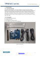
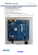
3.1. Hardware preparation and setup
Attach the included antenna to the SMA connectorJ21
Plug-in the included DC adapter to DC Jack J1
Or each UART to USB cable.
Plug-in 3FF SIM card to J17(back side of EVK)
Switch on S2(Power switch) to turn on the module.
There is no need to turn on S2 while using USB cable to power up EVK
Module PWR1 LED will be lighted when power EVK successfully. After modem boot up, the three
LED will be lighted.
Figure 3.1 LED status