Installation Instructions Listed Certified for USA and Canada Model Number: MQZDV1917 Stock #’s: MQZDV1917N, MQZDV1917LP, MQZDV1917NE, MQZDV1917LPE Certified to: ANSI Z21.88-2009, CSA 2.33-2009, CGA 2.17-M91 Zero Clearance Direct Vent Gas Fireplace This appliance may be installed in an aftermarket permanently located, manufactured home (USA only) or mobile home, where not prohibited by local codes. This appliance is only for use with the type of gas indicated on the rating plate.
Table of Contents Pre-installation Questions and Answers………………………………….. Operating Instructions………………………………………………………. Mobile Home/Manufactured Housing Installation……………………...... Warnings, Installations, and Operations………………………………….. Installation Requirements for the Commonwealth of Massachusetts… Fireplace Dimensions............................................................................ Locating your Appliance........................................................................
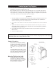
Pre-installation Questions and Answers About curing of the paint Your stove or fireplace has been painted with the highest quality silicone stove paint. This paint dries quickly in 15-20 minutes when first applied at the factory. However, due to the high temperature silicone components, the paint will cure when heat is applied to the appliance as it is first used. The following information applies to the curing process to get the paint fully hard and durable.
Mobile Home/Manufactured Housing Installation This Direct Vent System Appliance must be installed in accordance with the manufacturer’s installation instructions and the Manufactured Home Construction and Safety Standard Title 24 CFR, Part 3280, or the current Standard for Fire Safety Criteria for Manufactured Home Installations, Sites, and Communities ANSI/NFPA 501A, and with CAN/CSA Z240 MH Mobile Home Standard in Canada.
Warnings, Installations and Operations Installation Regulations This gas appliance must be installed by a qualified installer in accordance with local building codes, or in the absence of local codes, with the current CAN/CGA-B149.1 or .2 Installation Code (in Canada) or the current National Fuel Gas Code Z223.1 when installed in the United States.
• Gas fired appliances may be used only for supplemental heat and/or decorative purposes and under no circumstances shall they provide a primary heat source. • This appliance must not be connected to a chimney flue serving a separate solid-fuel burning appliance. NOTE: It is recommended that a Carbon Monoxide (CO) Detector be installed in or near bedrooms and on all levels of your home. Place a detector about 15ft [4.5m] outside the room that houses your gas appliance.
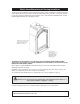
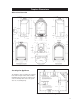
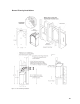
Fireplace Dimensions Dimensional Overview Figure 1 - An overview of the dimensions involved. Locating the Appliance The appliance can be located in the configurations shown in Figure 2. Note that an Island installation with a top vent is possible as long as the horizontal portion of the vent system does not exceed 20ft [6.1m]. Figure 2 - Possible fireplace location suggestions.
Framing for your Gas Fireplace This section will cover four different types of installations: General, Corner, Raised, and Cabinet installation. It is intended for qualified installers only. Before beginning, make note of where the gas and electrical accesses are located on the unit. This will streamline the construction process. Furthermore, familiarize yourself with the venting and clearance requirements (see Venting section) for this appliance.
Figure 3 - Figure 4 - Stud mount configuration Cabinet mount configuration. The Stud Mount configuration is for instances where facing material will be used. This includes drywall, granite, slate, marble, brick, and various other combustible and non-combustible materials. To mount the unit to a stud, simply bend the Back Tabs forward in the position shown in Figure 3. The Front Tabs maybe bent forward to clear a way for access to the screw holes.
General Framing Installations Figure 5 - General framing installation.
Corner Installations For Corner Installations the minimum clearance to combustibles in Table 1 must still be adhered to. Please refer to Figure 5 and the Clearance to Combustibles table for more information. In Figure 6, the minimum dimensions of a corner framing scenario is illustrated. Figure 6 - Corner Installation. Raised Installation For Raised Installations the minimum clearance to combustibles mentioned in Table 1 must still be adhered to.
Figure 7 - Cabinet installation. Note that the unit MUST be installed from the back of the cabinet. Figure 8 - Dimensions for facing material cutout.
Mantel Clearance Requirements Combustible materials may be installed right up to the stand-offs on the unit (see Standoff Locations). For mantels with combustible material please refer to Figure 9 below for clearance information. NOTE: Non-combustible mantels can be installed at any height above the fireplace vent opening. When using paint or lacquer to finish the mantel, such paint or lacquer must be heat resistant (250°F [121°C]) to prevent discoloration.
Sidewall Clearance Requirements Any installation with a sidewall (i.e. a wall perpendicular to the face of the unit) must adhere to the clearances imposed by the illustration shown in Figure 10. Figure 10 - Sidewall clearance requirements.
Facing Material Installation Guide The entire Facing Material for this unit may either be of combustible or non-combustible material. It is recommended that the Facing be installed after the unit is secured in its framing and properly vented. A cutout profile for this unit is shown in the Dimensional Overview section. NOTE: Only one 2x4 stud/header may be used in the frame. Please refer to Figure 5 on page 10 or Figure 11 below. Figure 11 - Installation guide for 1/2" facing material.
How to Install the Finishing Surround Figure 13 - Finishing Surround installation guide. 1. Make note of where the mount locations are. There should be four [4] places as shown in the illustration on the right. 2. Slide the Surround onto the unit. Rest the upper ledge of the Surround on top of the unit but below the Cabinet Shield. The Side Shields of the Surround should slide along the INSIDE face of the unit. 3.
How to Install the Access Panel Grill Figure 14 - Lower Access Panel installation and removal guide. 1. Lay the Finishing Surround on its face and position the Access Panel Grill in the fashion shown in Figure 14. Ensure that a soft cloth is placed underneath the Finishing Surround and the Access Panel Grill to avoid scratching. NOTE: By bending the Magnet Tabs back or forth, the alignment of the Lower Access Panel can be adjusted. However, excessive bending may result in the Magnet Tabs breaking. 2.
How to Install the Glass Door Figure 15 - Glass door installation guide. Removal Guide Remove the Arch Door (Please refer to page 19). Release the two [2] Lower Door Latches by pulling them out and over the Door Tabs. Unscrew the Upper Door Latches from the Glass Door. Slide the Door out and over the Slide Tabs. To install the Glass Door, simply reverse these steps. Glass Cleaning It will be necessary to clean the glass periodically.
How to Install the Arch Door Figure 16 - Arch Door mounting tab locations. 1. Ensure that the Lower Access Panel is in the OPEN position. Make note of the four [4] Mounting Tabs located on the unit [T1-T4], and the four [4] Mounting Slots on the Arch Door [S1-S4] (see Figure 16). 2. Slide the Arch Door into the unit as shown in Figure 17. Ensure that the upper portion of the frame is IN FRONT of the Upper Mounting Tab, and the lower portion is BEHIND the Lower Mounting Tab.
Fan Installation For new installations, it is recommended that the Fan Kit be installed prior to framing the fireplace. This can be accomplished by utilizing the Fan Access Cover shown in Figure 18. CAUTION: DO NOT ATTACH 120V FAN ASSEMBLY TO MILLIVOLT GAS VALVE SYSTEM. Figure 18 - Optional Fan Kit installation. Procedures for New Installations 1. Remove the Fan Access Cover mounting screws. Make note of how the Cover Edge is positioned on the inside of the unit rather than the outside. 2.
3. If the fan is working properly, you do not need to continue with these test procedures. 4. If the fan does not respond, check the wiring to ensure proper connections. See the Electrical Considerations section below for reference. Make note that the dark thick connection lines are BUS LINES that represents multiple lines and not one solitary connection. 5. Using a volt-meter, check the receptacle to verify that there is 120VAC 60Hz power available.
Figure 19 - Wiring diagram for a fan installation utilizing an unit-mount variable speed control. Baffle Replacement Guide This unit requires a baffle to operate properly and efficiently. The baffle is fastened with four [4] screws to the inside of the firebox. Please make note of their location before beginning the replacement procedure. IMPORTANT: Examine the condition of the mounting holes and screws. It is required that these areas are sealed properly.
Gas Line Installation This gas appliance should be installed by a qualified installer in accordance with local building codes and with current CAN/CGA - B149.1 or .2 installation codes for Gas Burning appliances and equipment in Canada and the National Fuel Gas Code ANSI Z223 in the U.S.A. 1. The gas pipeline can be brought in through either the left side or the bottom of the appliance. A knockout is provided at either location to allow for the gas pipe installation and testing of any gas connection. 2.
Burner Removal/Servicing Guide WARNING: FAILURE TO POSITION THE PARTS IN ACCORDANCE WITH THESE DIAGRAMS OR FAILURE TO USE ONLY PARTS SPECIFICALLY APPROVED WITH THIS APPLIANCE MAY RESULT IN PROPERTY DAMAGE OR PERSONAL INJURY. CAUTION: BEFORE STARTING REMOVAL OF PARTS TURN OFF GAS SUPPLY AND DISCONNECT ALL ELECTRICAL SUPPLIES. ALL WORK SHOULD BE PERFORMED BY A QUALIFIED AND CERTIFIED TECHNICIAN 1. Remove Glass Door, Logs, Rocks, and Embers.
Brick Liner Installation Guide The installation procedure for the Liners is common between the brick and porcelain. One should note however, that no matter which is installed it is imperative that the panels be positioned tightly against the walls of the firebox to ensure proper combustion and operation. CAUTION: Before operating the appliance, any screws removed from the firebox should be returned to the original position to ensure proper sealing. 1. Remove the glass door (see page 18). 2.
Porcelain Liner Installation Guide The installation procedure for the porcelain liner requires an additional mounting bracket: the Porcelain Rear Bracket. This bracket is used to position both sides and the rear panel in place. Note: It is imperative to position the panels tightly against the walls of the firebox to ensure proper combustion and operation of the appliance.
Millivolt System, Lighting, and Burner Control FOR YOUR SAFETY READ BEFORE LIGHTING WARNING: If you do not follow these instructions exactly, a fire or explosion may result causing property damage, personal injury or loss of life. A B BEFORE LIGHTING This appliance has a pilot which must be lighted by hand. When • Immediately call your gas supplier from a neighbour’s phone. Follow the lighting the pilot, follow these instructions exactly. gas supplier’s instructions.
Burner System Maintenance It is recommended to annually inspect and clean the Burner System to prevent malfunction and / or sooting. This operation should be performed by your dealer or a qualified technician. -CAUTIONBefore servicing the burner system ensure that the gas supply is turned OFF and disconnect all electrical connections to the appliance. Allow the appliance to cool to room temperature.
Conversion Kit Instructions -Part A Caution: The gas supply shall be shut off prior to disconnecting the electrical power, before proceeding with the conversion. WARNING: This conversion kit shall be installed by a qualified service agency in accordance with the manufacturer's instructions and all applicable codes and requirements of the authority having jurisdiction.
Gas Conversion for Top Convertible Pilot (Series 019065X) – PART B Instructions for converting SIT 190 series pilot burner injection from NG to LPG and from NG to LPG only. This information should be considered as supplemental to the Appliance Manufacturer’s Instructions. WARNING: The installation of this conversion kit must only be undertaken by a qualified and certified gas appliance installer. 1. Shut off the gas supply to the appliance. 2. Allow the pilot burner to cool to room temperature.
Gas Conversion for Modulator – PART C -WARNING!- -WARNING!- 31
IPI Electronic Ignition System Overview The IPI system is an advanced burner controller that provides you with the option of having either a Standing-Pilot, or an intermittent igniting system. This alternating mode is controlled by the CPI/IPI Switch (Continuous Pilot Ignition/Intermittent Pilot Ignition) located on the IPI System Box.
the slide switch to the middle [REMOTE] position and then push the small pushbutton to begin programming. Bring the transmitter close to the receiver and then press the power button [R] on the transmitter. An audible beep will sound to indicate the system is programmed and ready to be used. NOTE: The Remote Receiver module can also be located outside of the appliance to a maximum of 6ft away installed in a certified deep wall switch electrical box (2-3/4” depth).
Configuration #1: Basic manual HI/LO and manual ON/OFF capabilities.
Receiver Module .584.523/521/221 1001-P221SI Receiver Module .584.
IPI Lighting Instructions WARNING 1. If you do not follow these instructions exactly, a fire or explosion may result causing property damage, personal injury or loss of life. 2. Always light the pilot whether for the first time or if the gas supply has ran out with the glass door opened or removed. FOR YOUR SAFETY READ BEFORE LIGHTING A. This fireplace is equipped with an ignition device which automatically lights the pilot. Do not try to light by hand. B.
Venting A. B. C. D. E. F. G. H. I. J. Clearance above grade, veranda, porch, deck, [1,2] or balcony 12in [30cm] min. Clearance to window or door that may be opened. 12in [30cm] min. for appliances 100,000BTUh [30kW] and lower, in Canada. [2] 9in [23cm] for appliances 50,000 BTUh and lower, in USA. Clearance to permanently closed window min. 12in [30cm] recommended to prevent condensation on window, in Canada. 9in[2] [23cm] for appliances 50,000 BTUh and lower, in USA.
Termination It is imperative that the vent termination be located observing the minimum clearances as shown. There must not be any obstruction such as bushes, garden sheds, fences, decks or utility buildings within 24" from the front of the termination plate. Do not locate termination where excessive snow or ice build-up may occur. Be sure to check vent termination area after snow falls and clear to prevent accidental blockage of venting system.
Horizontal Vent Table To use the Horizontal Vent Table (see Table 2), determine the total vertical height of the system and the number of bends required. Locate the value on the first column and then move across to see the corresponding maximum allowable horizontal run. The Horizontal Vent Table has been established for 90o horizontal/vertical runs. Therefore, flex pipes that do not have 90o bends will not fall into this vent table relationship. Total Vertical Max. Horizontal Total Vertical Max.
Figure 24 - Venting configuration illustrating vertical rise over 4ft horizontal run. General Vent Installation Information WARNING: DO NOT mix parts from different systems unless stated in the manual. Flex Pipe Venting Flex pipe is shipped in an unexpanded length. Therefore, when installing the pipe, expand it completely and then cut off the remaining length. A flex pipe can be expanded to twice their shipped length (e.g. 4ft. to 8ft). Do not use more than 2 couplers to extend short pipes.
Figure 25 - Flex pipe spring spacing guide. Horizontal runs require support metal straps every 2ft. In an offset installation support straps should be used to stabilize pipe. Expand 4" and 7" flex pipe to the point that the 7" protrudes approximately 2 to 3 inches past outer wall and the 4" flex protrudes approximately 2 to 3 inches past the 7" flex. Attach the 4" pipe to the termination first and secure with sealant and four screws then attach the 7" flex to the termination with caulking and four screws.
Before joining pipes, apply a bead of high temperature sealant (Mill Pac) to end of pipe. First attach the 4" flue pipe to the vent termination with sealant, and secure with the four screws provided. At this time make sure the spacer springs are attached to the 4" flex pipe as required. Then attach the 7" pipe by the same method. Figure 26 - Side wall hole dimensions for flush wall installations.
Maximum vertical height of system should not exceed 40 feet [12.2m]. Use roof support and 7" rigid pipe at roof level. Flex not permitted within roof support. When penetrating the roof a rigid 7" galvanized pipe must be used. Attach the 7" flex to the 7" rigid with high temperature sealant, secure with four screws assuring the flex and rigid pipe are secured. 4" flex pipe must be secured the same way with 4 screws but must penetrate the 4" flex and 4" section of termination.
Figure 28 - a) Straight-through roof support configuration; b) Flex bend configuration; c) Termination mounting. Roof Flashing Ensure that you have the proper roof flashing by checking your roof pitch using a level and two rulers, or by using a roof pitch card (see Figure 28a). Slide a Roof Flashing suitable to your roof slope over the vent. Place the edge of the flashing plate that will be on the higher part of the roof slope under the shingles.
Log C-19 Placement Instructions WARNING: Logs must be place at their proper locations as shown in these illustrations. Failure to do so will result in improper combustion and emission of harmful gases, and can lead to personal injuries. Figure 29 - Log C-19 parts list. Figure 29 - Log C-19 parts list. Figure 31 - Step 1. Place LOG #1 on the right side of the burner as shown. Figure 32 - Step 2. Place LOG #2 on the firebox bottom log placement tab as shown.
Figure 33 - Step 3. Place LOG #3 onto the Log Placement tab located on the ember plate as shown. Figure 34 - Step 4. Place LOG #4 on the sides of LOG #2 and #3 as shown. Figure 35 - Step 5. Place Ember Rocks on the front burner tube and ember plate as shown. DO NOT PLACE EMBER ROCKS ON THE REAR BURNER TUBE. Figure 36 - Step 6. Place Lava Rock on the bottom of the firebox IN FRONT and around the side of the burner tube. Sprinkle Vermiculite over top of the lava rock (for decoration only).
Parts List Serenity Zero Clearance Direct Vent Gas Fireplace – 19” Wide GFRC Remote Control On/Off GTRC Remote Control - Thermostat GTMRCN Remote Control – Thermostat / Modulating – NG GTMRCP Remote Control – Thermostat / Modulating – LP GTFRCN Remote Control – Thermostat / Modulating / Fan – NG Fireplace Heater; Milli Volt (as above) Propane; 17,000 BTU GTFRCP Remote Control – Thermostat / Modulating / Fan – NG Approved for bedroom & mobile home.
Miscellaneous Parts (Continued) ZDV7FC Flex Connector 7" Diameter Spring 4" Standoff Spacer Simpson Dura-Vent Adapter 1000-255 #ORIFICE BRASS (State Size) ZDV4SS 1000-EMBER #DECORATIVE ROCK ZDVDKA 2000-080 #THERMODISC 2450 (For Blower) 6000-P930 #BLOWER MOTOR QLN65/0018 2000-085 #CONTROL VARIABLE SPEED KBWC13BV 1000-306 THERMALCORD – W/ADHESIVE 19ZDV-301 DOOR FRAME 19ZDV-310 CERAMIC GLASS 19MQ-P3815 STAINLESS STEEL GAS LINE 36HB-123 UPPER DOOR SPRING Kingsman Fireplace Venting ZDVHS
Troubleshooting the Gas Control System WARNING BEFORE DOING ANY GAS CONTROL SERVICE WORK, REMOVE THE GLASS FRONT. Before troubleshooting the gas control system, be sure external gas shut off is in the "On" position. Problem Spark igniter will not light. Possible Causes Corrective Action Defective or misaligned electrode at pilot. Check for spark at electrode and pilot: if no spark and electrode wire is properly connected, replace igniter. Defective igniter (pushbutton). Using a match, light pilot.
LIMITED LIFETIME WARRANTY This Limited Lifetime Warranty applies only while the unit remains at the site installation and only if the unit is installed inside the continental United States, and Canada. The warranty applies only if the unit is installed and operated with the printed instructions and in compliance with applicable installation and and good trade practices.