
Operating instructions


Conversion Kit Instructions -Part A
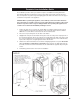
WARNING: This conversion kit shall be installed by a qualified service agency in accordance
with the manufacturer's instructions and all applicable codes and requirements of the authority
having jurisdiction. If the information in these instructions is not followed exactly a fire, explosion or
production of carbon monoxide may result causing property damage, personal injury or loss of life.
The qualified service agency is responsible for the proper installation of this kit. The installation is
not proper and complete until the operation of the converted appliance is checked as specified in
the manufacturer's instructions supplied with kit.
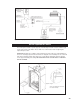
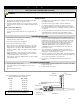
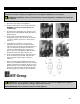
Figure 23 - Burner tube removal.
1. Remove the Grate Bar Assembly and Burner Hold Down.
2. Slide the Burner Tube to the right and remove it from the assembly. Make note of where the
Air Shutter is and the screw used to secure it.
3. Remove the main orifice using a 1/2” wrench and replace it with the new conversion kit orifice.
4. Install new pilot orifice and Hi/Lo valve regulator by following the instructions supplied with the
conversion kit (see Section B on the next page).
5. Adjust the primary air setting by changing the Air Shutter opening to the configuration specified
in the manual (see page 28) or on the label plate. To adjust the air setting, loosen the screw on
the Air Shutter and then rotate it to the correct opening. A drill bit or a tape measurer can be
used as a gauge. Retighten the screw once the shutter is properly adjusted.
6. Reinstall the Burner Tube and Grate assembly by reversing steps 1 & 2.
7. Attach the new labels onto the bottom of the unit, writing information as needed.
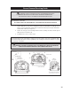
Caution:
The gas supply shall be shut off prior to disconnecting the electrical power, before proceeding
with the conversion.
29