Seresco: (pronounced Sir-ES-co) meaning “to become dry” Installation and Operation Manual NE Series Dehumidifiers For NE-004-016 Models: PV, NV, PH and NH Configuration Natatorium Dehumidifiers NC Series Outdoor Air-cooled Condensers 1
CAUTION ONLY TRAINED, QUALIFIED PERSONNEL SHOULD INSTALL AND/OR SERVICE SERESCO EQUIPMENT. SERIOUS INJURY AND PROPERTY DAMAGE CAN RESULT FROM IMPROPER INSTALLATION/SERVICE OF THIS EQUIPMENT. HIGH VOLTAGE ELECTRICAL COMPONENTS AND REFRIGERANT UNDER PRESSURE ARE PRESENT 1-888- SERESCO (737-3726) Additional copies of this manual can be downloaded from: www.seresco.
TABLE OF CONTENTS 1. Introduction ...................................................................………………...................…… 1.1 Packaged Mechanical Refrigeration Systems............................................….........…… 1.2 NE Series Dehumidifier features……..............................................….........…………… 2. Installation .................................................................................………….…………….. 4 5 6 7 2.1 Uncrating and Inspecting..................................
1. Natatorium: a facility that contains an indoor pool, whirlpool or spa ranging in size from a small residential installation to a large commercial indoor waterpark. engineering issues to the more subtle details in the air distribution. Experience and a complete understanding of the design issues help the designer satisfy: Seresco’s Natatorium Dehumidifiers were developed by a team of industry experts with a lifetime of experience developed while working with many thousands of indoor pools.
The type of facility being designed dictates the space temperature. Table 1 helps target some typical conditions. It is critical to understand who will be using the facility in order to deliver the conditions most likely to satisfy them. 1.1 Packaged mechanical refrigeration system.
1.2 NE Series Dehumidifier Features. Figure 3 identifies where several major components are located within the NE Series unit. 5 - Blower. Plug fans are standard on all units. The backward inclined airfoil blower wheel provides high static pressure with low motor power. This feature helps ensure the NE unit will perform to specifications even if the duct connections to the unit or if the overall duct installation are less than ideal.
2. Installation 2.1 Uncrating and Inspecting Seresco inspects and fully tests each dehumidifier in all operating modes before it ships from the factory. The unit can suffer damage in transit. Check the equipment thoroughly for both visible and concealed damage before you sign the receiving papers. Document any damage in writing on the carrier’s bill of lading to ensure that damage claims are handled promptly. If the unit has been damaged, obtain a claim form from the carrier.
2.3. High Voltage Electrical Connections The installing contractor must ensure that all electrical wiring satisfies all National, State and Local codes. The microprocessor has been programmed to control their operation. Figure 8 illustrates how an Ethernet connection to the Internet allows all functions to be monitored by trained professionals with Seresco’s Websentry. It is the final step to ensure the facility operates trouble free. 2.3.
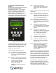
2.5 Controller, Programming and Sensors The NE Series Command Center (Figure 9) is the brains behind the NE Series Dehumidification System. The Command Center is composed of a microcontroller system, an LCD display and keypad, an Ethernet interface, and WebSentry – a web browser based remote interface tool for monitoring and controlling NE Series systems from anywhere in the world via the internet Enter Press to save changes to parameters and (optionally) press again to return to the main sensor screen.
2.5.1 Normal Mode: Menus and selections are accessed using the “1-6” numbered keys – each menu item and parameter is preceded by a number from 1 to 6. When the scroll keys can be used to access additional menu items they will appear on the screen ( and ). The same scroll keys are used to change values after a parameter has been selected. A User Password is required to view/change setpoints and schedules.
2.5.2 Service Mode 2.5.4 System Status From the Startup Menu there is a Service Mode available for factory trained service technicians. Please contact factory for additional information. The CommandCenter has a feature which will provide more detailed information about the internal operation of the system, which can assist an owner or service technician in understanding his NE Series unit is doing at any given moment. 2.5.
2.5.5 Sensors and location. Figures 11 & 12 identify where the sensors are located in the NE Series units. Each sensor is accessible through the Command Center or Web Sentry. Sensor history is stored and can be reviewed in tabular form. All Sensors can be calibrated in service mode.
2.6. System Design Checklist. Ensuring that all critical system design aspects have been addressed is paramount to obtaining a safe and healthy pool environment. Seresco’s name is a useful checklist. System duct design and air pattern Evaporation rate and latent loads Required Access Space Exhaust Air Supply Air flow Cooling and Heating loads Outdoor Air 2.6.
Figure 14 – Perimeter Below Grade Duct Layout General Recommendations: Galvanized sheet metal ducts are acceptable in most installations. A below-grade duct system should use PVC or plastic-coated galvanized spiral pipe to avoid deterioration. Ductwork that passes through an unconditioned area should be insulated on the exterior. When applicable, locate exhaust fan air intakes as close to the whirlpool as possible.
2.6.4 Exhaust Air. ASHRAE recommends the room be maintained at 0.05-0.15” WC negative pressure relative to surrounding spaces. Ten percent more exhaust air than outdoor air is a good rule of thumb. Figure 16 illustrates how the location of the exhaust fan can also significantly improve the air quality in the space. A spa or whirlpool should have the exhaust air intake grille located directly above it.
dry portion of the deck will not factor into the IAQ issues. The NE Series units have an outdoor air opening with a filter and manual balancing damper. Optional unit mounted motorized dampers and time clocks are available. Figure 17 illustrates a typical connection configuration. entire cabinet is under negative pressure. Without a trap, condensate will not drain and the unit will overflow into your mechanical room.
Figure 19 – Proper Pool Water Piping Installation 17
2.9. Outdoor Air Cooled Condenser Installation. This condenser is used in air conditioning mode where it rejects unneeded heat from the space to outdoors. Proper installation is essential to ensure it can function as intended. Proper airflow and refrigerant piping are paramount. Ensure an appropriate maximum ambient air temperature has been specified. Ensure the unit has proper airflow per Figure 20. A perimeter of free area equal to its width must be provided. Use line sizes as specified by Seresco.
Figure 21 – Typical Outdoor Condenser Installation NE Model Factory Charge (Lbs) 50’ line contractor charge (Lbs) Factory Oil Charge (Oz) 004 25 17 9 005 27 28 12 006 27 29 12 007 28 32 14 008 44 32 15 010 48 48 20 012 51 62 29 014 61 77 35 Table 5 - R-22 and Oil Charges 2.9.2 Charging of Remote Condensers Once a proper evacuation has been accomplished the system is ready for charging. The outdoor air-cooled condenser requires a field charge by the installing contractor.
4. There is an access valve in the liquid line after the pump down valve. The pump down valve can be manually closed during start-up mode via the controller. Add only as much refrigerant as is needed to get to the total charge indicated on the nameplate. Never charge liquid into the suction line access valve! 5. The receiver has 2 sight glasses with float balls to help ensure the maximum and minimum refrigerant levels are easily met. 3.0 Pool Water Chemistry.
4. Start-up Procedures 4.1. Pre Start-up A complete start-up is required to ensure all systems have been setup and adjusted to ensure optimum and reliable unit operation. The final adjustment and balancing must be done when all space and water temperatures are at design conditions. The use of auxiliary or portable air heaters may be required to heat the room. Read this section thoroughly before attempting to commission the Seresco dehumidifier. NOTE: Do not use the unit as a construction site heater.
4.3. System Operation Modes The standard sequence of operation for a Seresco dehumidifier is relatively simple. Whenever the compressor operates the evaporator coil is active where it absorbs heat from the warm, humid air stream. The cooling process at the evaporator coil drops the air well below its dew point and thereby dehumidifies the air. Whenever the compressor operates the evaporator is always dehumidifying and cooling the return air.
4.3.6 Compressor Start Sequence All NE units have a pump down sequence and anti-short cycle timer. When a demand requires the compressor to operate the following sequence occurs: Blower operation confirmed by microprocessor and ASCT sequence completed. Pump down solenoid opens. 50 psig will close the low pressure safety switch contact. Compressor starts. 4.3.
Verify that the TX Valve and solenoid valves are free of debris. Clean or replace them as necessary. Replace the suction filter with a suction line filter-drier designed specifically for cleaning system burnouts (Sporlan “HH” series or equivalent). Select filters that are equipped with a tap for measuring the pressure drop across the filter. Remove the old liquid line filter-drier and replace it with a new filter one size larger than the original.
6.2.
Head pressure too low Return air % RH level too low Low Suction pressure Normal: 60 – 75 PSIG Insufficient evaporator air flow Blocked filter drier Expansion valve not feeding properly Restriction in refrigeration piping Check piping for kinks Compressor discharge service valves closed or not fully open Fully open service valves Excessive refrigerant charge Check receiver sight glasses – level indicators.
Poor air distribution Unit operates but windows have condensation Airflow across evaporator is too high. Coil only doing sensible cooling Unit is undersized Air and/or pool water temperature incorrect Pool Water Heating (PH and PV Models) Low water temperature rise High water temperature rise Compressor runs for short periods and shuts off Conditions are being satisfied quickly Low Supply Air Temperature rise in Dehumidification Mode Too much airflow through unit.
6.4 Airflow Adjustment Procedure 6.5. Basic Unit Operation 6.4.1 Supply Airflow adjustment. All Seresco units have internal airflow balancing ports. When removed, each port internally recirculates approximately 5% of the unit airflow. This is a quick and simple way to adjust the supply airflow. The plugs and their location are shown in Figure 26. 6.5.1 Controller Set Points All NE units have been selected based on predetermined operating conditions for each facility.
Typical Unit Performance (For R 22 units) Dehumidification Air Conditioning Water Heat & AC Water Heat & Dehumidification Supply Air Temperature change + (10 – 15)ºF - (10 – 15)ºF - (10 – 15)ºF + (0 – 3)ºF Air off evaporator 47- 55ºF 47- 55ºF 47- 55ºF 47- 55ºF Leaving Water Temperature change 0 ºF 0 ºF + (8 – 10)ºF + (8 – 10)ºF Suction - PSIG 60 - 80 60 - 80 60 - 80 60 - 75 High - PSIG 200 - 265 200 - 290 200 - 240 200 - 240 Table 8 – Typical Operating Parameters 6.6.
6.7 Warranty General Policy This warranty applies to the original equipment owner and is not transferable. Seresco Inc. warrants as set forth and for the time periods shown below that it will furnish, through a Seresco Inc. authorized installing contractor or service organization, a new or rebuilt part for a part which has failed because of defect in workmanship or material. Seresco Inc.
Limitations This warranty is given in lieu of all other warranties. Anything in the warranty notwithstanding, any implied warranties of fitness for particular purpose and merchantability shall be limited to the duration of the express warranty. Manufacturer expressly disclaims and excludes any liability for consequential or incidental damage for breach of any express or implied warranty.
6.
6.9 Field Wiring Diagram 6.
6.
Outdoor Air cooled condenser or Dry Cooler location: ……. ft [above / below] Seresco unit If above, oil traps installed: [yes / no] Same Level as Seresco Unit Condenser/Dry Cooler Model installed:…………………………. Water Cooled and Dry Cooler AC Fluid GPM……………………….. Glycol %:………………………… Glycol stabilizers added: [yes / no] Piping and valves installed per Specs? Total line length to OACC or Dry Cooler…………………………. Hot gas line size……………….….. Liquid line size……………………..
Your local Seresco representative: Design Checklist System design and air flow pattern Evaporation rate and latent loads Required Access Space Exhaust Air Supply Air Cooling and Heating loads Outdoor Air Project: ____________________________________________________________________ Reviewed by: ________________________________________________________________ System design and air flow pattern All exterior windows, doors and skylights are fully blanketed with supply air.