
Specifications


28
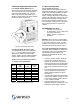
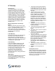
6.4 Airflow Adjustment Procedure
6.4.1 Supply Airflow adjustment. All
Seresco units have internal airflow balancing
ports. When removed, each port internally
recirculates approximately 5% of the unit
airflow. This is a quick and simple way to
adjust the supply airflow. The plugs and their
location are shown in Figure 26.
Figure 26 - Airflow adjustment plugs
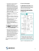
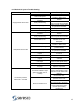
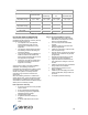
6.4.2 Internal Static Pressures (ISP).
The standard NE Series unit is configured
for ¾” - 1” External Static Pressure (ESP)
depending on options. Should the ESP
change, Table 7 can help evaluate whether
a blower wheel change may be required.
Contact Seresco if there is more than a
½” change in the system ESP.
Model
Design
TSP
(“WC)
ISP
(“ WC)
ISP with
heating
coil
004
1.8 0.8 1.1
005
2.1 1.1 1.4
006
2.3 1.3 1.6
007
2.5 1.5 1.8
008
2.0 1.0 1.3
010
2.4 1.4 1.7
012
3.0 2.0 2.3
014
2.4 1.4 1.7
Table 7 - Internal Static Pressures (“ WC)
6.5. Basic Unit Operation
6.5.1 Controller Set Points
All NE units have been selected based on
predetermined operating conditions for each
facility. Most operating conditions fall within
the parameters suggested in Table 1 on
page 5. Changing setpoints can significantly
increase the evaporation load from the pool.
Before making significant changes (more
than 2ºF) to the setpoints indicated on the
unit nameplate, contact factory to verify that
the resulting load does not exceed unit
capacity.
R
ECOMMENDED SET POINTS:
Humidity: 50% to 60% RH.
Air temperature: 2º
to 4º F above the
pool water temperature.
Refer to Table 1 on page 5 for
guidelines.
W
ARNING: Never shut down a dehumidifier.
Even when not in use, pool water continues
to evaporate moisture to the air. It is also
prudent to cover the pool if the facility is to
be unattended for longer periods of time.
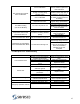
6.5.2 Typical Unit Operation Parameters.
There are several variables that impact unit
performance. If the unit is operating within
the parameters listed in Table 8, the
systems are well balanced and the unit is
performing well.
These are “Rule of Thumb” guidelines
only and do not include outdoor air.
Outdoor air would need to be shut off
fully during the time of the measurement
or be factored into these values based
on its exact conditions at the time of the
test.
The indicated refrigerant pressures are
the most important to target as they
directly impact all aspects of system
performance.
If any operating parameters are outside
those listed in Table 8 on page 29, refer
to the trouble-shooting guide in section
6.3 for possible solutions.
Suction temperature once unit has
stabilized should not exceed 75ºF or be
below 55ºF under normal conditions.