
Specifications

9/27/01 AC 43.13-1B CHG 1
Par 11-67 Page 11-25
11-67. METHODS FOR DETERMINING
CURRENT CARRYING CAPACITY OF
WIRES
. This paragraph contains methods for
determining the current carrying capacity of
electrical wire, both as a single wire in free air
and when bundled into a harness. It presents
derating factors for altitude correction and ex-
amples showing how to use the graphical and
tabular data provided for this purpose. In
some instances, the wire may be capable of
carrying more current than is recommended for
the contacts of the related connector. In this
instance, it is the contact rating that dictates
the maximum current to be carried by a wire.
Wires of larger gauge may need to be used to
fit within the crimp range of connector con-
tacts that are adequately rated for the current
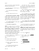
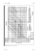
being carried. Figure 11-5 gives a family of
curves whereby the bundle derating factor may
be obtained.
a. Effects of Heat Aging on Wire Insula-
tion. Since electrical wire may be installed in
areas where inspection is infrequent over ex-
tended periods of time, it is necessary to give
special consideration to heat-aging character-
istics in the selection of wire. Resistance to
heat is of primary importance in the selection
of wire for aircraft use, as it is the basic factor
in wire rating. Where wire may be required to
operate at higher temperatures due either to
high ambient temperatures, high-current load-
ing, or a combination of the two, selection
should be made on the basis of satisfactory
performance under the most severe operating
conditions.
b. Maximum Operating Temperature.
The current that causes a temperature steady
state condition equal to the rated temperature
of the wire should not be exceeded. Rated
temperature of the wire may be based upon the
ability of either the conductor or the insulation
to withstand continuous operation without deg-
radation.
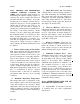
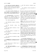
c. Single Wire in Free Air. Determining
a wiring system’s current carrying capacity be-
gins with determining the maximum current
that a given-sized wire can carry without ex-
ceeding the allowable temperature difference
(wire rating minus ambient °C). The curves
are based upon a single copper wire in free air.
(See figures 11-4a and 11-4b.)
d. Wires in a Harness. When wires are
bundled into harnesses, the current derived for
a single wire must be reduced as shown in fig-
ure 11-5. The amount of current derating is a
function of the number of wires in the bundle
and the percentage of the total wire bundle ca-
pacity that is being used.
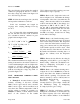
e. Harness at Altitude. Since heat loss
from the bundle is reduced with increased al-
titude, the amount of current should be de-
rated. Figure 11-6 gives a curve whereby the
altitude-derating factor may be obtained.
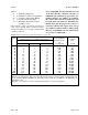
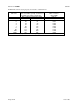
f. Aluminum Conductor Wire. When
aluminum conductor wire is used, sizes should
be selected on the basis of current ratings
shown in table 11-10. The use of sizes smaller
than #8 is discouraged (Ref. AS50881A).
Aluminum wire should not be attached to en-
gine mounted accessories or used in areas
having corrosive fumes, severe vibration, me-
chanical stresses, or where there is a need for
frequent disconnection. Use of aluminum wire
is also discouraged for runs of less than 3 feet
(AS50991A). Termination hardware should be
of the type specifically designed for use with
aluminum conductor wiring.
11-68. INSTRUCTIONS FOR USE OF
ELECTRICAL WIRE CHART.
a. Correct Size. To select the correct size
of electrical wire, two major requirements
must be met: