
Specifications


9/27/01 AC 43.13-1B CHG 1
Par 11-85 Pages 11-39
SECTION 7. TABLE OF ACCEPTABLE WIRES
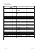
11-85. AIRCRAFT WIRE TABLE. Ta-
bles 11-11 and 11-12 list wires used for the
transmission of signal and power currents in
aircraft. It does not include special purpose
wires such as thermocouple, engine vibration
monitor wire, fiber optics, data bus, and other
such wire designs. Fire resistant wire is in-
cluded because it is experiencing a wider ap-
plication in aircraft circuits beyond that of the
fire detection systems.
a. All wires in tables 11-11 and 11-12
have been determined to meet the flammability
requirements of Title 14 of the Code of Federal
Regulation (14 CFR) part 25, section
25.869(a)(4) and the applicable portion of
part 1 of Appendix F of part 25.
b. The absence of any wire from ta-
bles 11-11 and 11-12 are not to be construed as
being unacceptable for use in aircraft. How-
ever, the listed wires have all been reviewed
for such use and have been found suitable, or
have a successful history of such usage.
c. Explanations of the various insulation
materials mentioned in table 11-11, by abbre-
viations, can be found in the glossary.
11-86. OPEN AIRFRAME INTERCON-
NECTING WIRE. Interconnecting wire is
used in point to point open harnesses, normally
in the interior or pressurized fuselage, with
each wire providing enough insulation to resist
damage from handling and service exposure.
(See table 11-11.) Electrical wiring is often in-
stalled in aircraft without special enclosing
means. This practice is known as open wiring
and offers the advantages of ease of mainte-
nance and reduced weight.
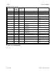
11-87. PROTECTED WIRE. Airborne
wire that is used within equipment boxes, or
has additional protection, such as an exterior
jacket, conduit, tray, or other covering is
known as protected wire. (See table 11-12.)
11-88. SEVERE WIND AND MOISTURE
PROBLEMS (SWAMP). Areas such as
wheel wells, wing fold and pylons, flap areas,
and those areas exposed to extended weather
shall dictate selection and will require special
consideration. Insulation or jacketing will vary
according to the environment. Suitable wire
types selected from MIL-W-22759 shall be
used in these applications. (See table 11-11.)
Suitable wire types selected from
MIL-W-22759 are preferred for areas that re-
quire repeated bending and flexing of the wire.
Consideration should be made to areas that re-
quire frequent component removal or repair.
(See table 11-11.)
11-89. SHIELDED WIRE. With the in-
crease in number of highly sensitive electronic
devices found on modern aircraft, it has be-
come very important to ensure proper shield-
ing for many electric circuits. Shielding is the
process of applying a metallic covering to
wiring and equipment to eliminate interference
caused by stray electromagnetic energy.
Shielded wire or cable is typically connected to
the aircraft’s ground at both ends of the wire,
or at connectors in the cable. Electromagnetic
Interference (EMI) is caused when electro-
magnetic fields (radio waves) induce high-
frequency (HF) voltages in a wire or compo-
nent. The induced voltage can cause system
inaccuracies or even failure, therefore putting
the aircraft and passengers at risk. Shielding
helps to eliminate EMI by protecting the pri-
mary conductor with an outer conductor. Re-
fer to MIL-DTL-27500, Cable, Power, Electri-
cal and Cable Special Purpose, Electrical
Shielded and Unshielded General Specifica-
tions.