
Specifications

9/8/98 AC 43.13-1B
Par 11-135 Page 11-55
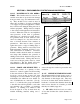
SECTION 10. SERVICE LOOP HARNESSES (Plastic Tie Strips)
11-135. GENERAL. The primary function
of a service loop harness is to provide ease of
maintenance. The components, mounted in
the instrument panel and on the lower console
and other equipment that must be moved to
access electrical connectors, are connected to
aircraft wiring through service loops. Chafing
in service loop harnesses is controlled using
the following techniques.
11-136. SUPPORT. Only string ties or
plastic cable straps in accordance with para-
graph 11-158 should be used on service loop
harnesses. A 90° or “Y” type spot tie should
be installed at the harness breakout point on
the harness bundle. Ties should be installed
on service loop harnesses at 4 to 6-inch inter-
vals.
11-137. ANTI-CHAFING MATERIAL.
When service loops are likely to be in contact
with each other, expandable sleeving or
equivalent chafe protection jacket material
must be installed over service loop harnesses
to prevent harness-to-harness chafing. The
sleeve should be held in place with string ties
at 6 to 8-inch intervals. Harness identification
labels should be installed, with string tie,
within 3 inches of the service loop harness in-
stallation.
11-138. STRAIN RELIEF. The strain re-
lief components may be installed to control
routing where close clearance exists between
termination and other components or bulk-
heads. Strain relief components provide sup-
port of the service loop harness at the termina-
tion point. Connector strain relief adapters,
heat-shrinkable boot, or a length of heat-
shrinkable tubing should be installed. The
heat-shrinkable boots will provide preselected
angles of wire harness termination when heat
is applied. Heat-shrinkable tubing should be
held at the desired angle until cool.
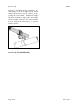
11-139. “SERVICE LOOP.” Primary sup-
port for service loop harness(es) should be a
cushion clamp and a connector at the harness
termination. Service loop harnesses should be
inspected for the following:
a. Adequate Length. Components
should extend out from their mounting posi-
tion a distance that permits rotating and un-
locking (or locking) the electrical connector.
Usually a distance of 3 to 6 inches, with all
other components installed, should be suffi-
cient.
b. Bundle BreakOut Point.
(1) Bundle breakout point should be
adequately supported with string tie.
(2) Service loop must maintain a mini-
mum bend radius of 3 times the harness di-
ameter.
(3) The breakout point should be lo-
cated directly behind, beside, below, or above
the component so that the service loop harness
does not bind other components.
(4) Plastic ties should not be used be-
tween the service loop breakout and the elec-
trical connector when they are likely to chafe
against adjacent wire.