
Specifications


AC 43.13-1B CHG 1 9/27/01
Page 11-88 Par 11-220
doliers, are heated in an infrared heating tool
that processes the markers for permanency.
The typed and heat-treated markers remain on
the bandolier until ready for installation.
b. Markers are normally installed using
the following procedure:
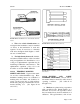
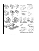
FIGURE 11-28. Cable markers.
(1) Select the smallest tie-down strap
that will accommodate the outside diameter of
the cable. (See table 11-22.)
(2) Cut the marking plate from the
bandolier. (See figure 11-28.)
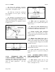
(3) Thread the tie-down straps through
holes in marking plate and around cable.
Thread tip of tie-down strap through slot in
head. (See figure 11-29.) Pull tip until strap
is snug around cable.
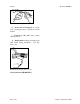
FIGURE 11-29. Tie-down strap installation.
T
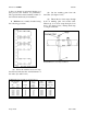
ABLE 11-18. Selection table for standard sleeves.
Wire or Cable
Diameter Range.
(inches)
Min Max
Markable
Length *
(inches)
Installed
Sleeve
Length
(nom)
(inches)
Installed
Wall
Thickness
(max inches)
As-supplied
Inside
Diameter
(min inches)
0.050 0.080
0.075 0.110
0.100 0.150
0.135 0.215
0.200 0.300
0.135 0.300
0.260 0.450
18
18
18
18
18
18
18
1.5
1.5
1.5
1.5
1.5
1.5
1.5
0.026
0.026
0.028
0.028
0.028
0.028
0.028
0.093
0.125
0.187
0.250
0.375
0.375
0.475
* Based on 12 characters per inch