DTS-2 Radio Control System 3-channel, 2.
3 2 Table of Contents 1.1 Transmitter introduction 4 Transmitter 5 Binding, Inserting batteries, connecting sytem 6 2.1 Specifications 6 2.2 Menu introduction 8 2.3 Main Function 2.4 EPA 9 2.5 D/R 2.6 S-Trim 10 2.7 Rev 10 2.8 ST CURV 11 2.9 TH CURV 13 2.10 ABS 14 2.11 MODEL 15 2.12 Speed 16 2.13 ATS 17 2.14 BK-Mix 18 2.15 Mix 2.16 TH Hold 19 2.17 F/S 2.18 Neutral 20 2.19 Sound 2.20 RESET 2.21 M-RES 21 2.22 TIMER 22 3.
Dragon-Rc radio DTS-2 3-Ch 2.4G Radio Control System Introduction Thank you for purchasing the Dragon-RC DTS-2 3-Ch 2.4GHz Radio Control System Before using, read this manual carefully. Updated info and manuals can be found on: www.dragon-rc.
ANTENNA ST.TRIM LCD BACK STEERING TENSION ADJUSTMENT AUX LOCK ROLLING SELECTOR ST.D/R ST.TRIM TH.HOLD STEERING WHEEL TH.
Warning: 1. This product is equipped for radio controlled models only. 2. We will not be responsible for the (ab)use, damages caused by unauthorized modification, adjustment or replacement of parts of this product; 3. The manual may be altered without prior notice. Please contact us if you have any corrections or clarifications that should be made in the manual. 4. Please pay extra attention to the parts in this manual, which are marked with ‘Warning’. 5.
2.1 Specifications 6 Function 5.0V 1: EPA 2: D/R 3: S-TRIM 4: REV 5: ST CURV Function 5.0V 11: BR-MIX 12: MIX 13: TH HOLD 14: F/S 15: NEUTRAL Function 5.0V 6: TH CURV 7: ABS 8: MODEL 9: SPEED 10:ATS Function 5.0V 16: SOUND 17: REST 18: M-RESET 19: TIMER - 3 Channels - End Point Adjustment - Supports dual rate function for the STEERING - Sub-trim for THROTTLE channel and STEERING channel - Model name can use up to 5 letters and numbers, so recognisable names can be set.
2.2 Menu INTRODUCTION D/R (page 9) EPA (page 8) ST D/R 10.2V EPA 10.2V ST TH AUX POS 0: POS 1: F: 00% 120% 100% B: 00% 120% 100% S-TRIM (page 9) ATS 10.2V 70% 100% REV (page 10) S-TRIM 10.2V REVERSE 10.2V ST: 0 REV TH: 0 MIX 10.2V NOR ST TH AUX ST CURV (page 10) ST EXP 10.2V M: EXP R: 0% TH CURV (page 11-12) TH-CURV 10.2V TH-CURV 10.2V TH-CURV 10.2V M: EXP M: CURV 1 2 3 R: 88 BR: 0 M: VRT P: 50 R: 25 BR: 0 MODEL 10.2V MDL.N: R: 43 ABS (page 13) ABS 10.
ATS (page 16) SPEED (page 15) SPEED 10.2V SPEED 10.2V ST ST TH ATS 10.2V TH SPD.FL: 0% SPD.FL: 0% SPD.BK: 0% TRI: POS: DLY: MOD: ATS 10.2V 1% 0% 0% INH BK-MIX 10.2V EN: 80% ON OFF MIX 10.2V MIX 10.2V ST: L50 R50 TH: L50 R50 EN: ON OFF ST: L50 AUX: L60 EN: ON 1% 0% 0% ACT R50 R50 OFF F/S (page 19) TH HOLD (page 18) TH-HOLD 10.2V MIX 10.2V MIX 10.
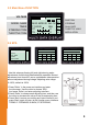
2.3 Main Menu FUNCTION VOLTAGE 5.0V MODEL NAME TIMER STEERING TRIM THROTTLE TRIM SBT: 0 16 D/R: 100 HLD: OFF MOD: HRF SUB TRIM LOCK LOCK M 00: MOD 00 ALL T-1:00:00 INH ST 0 TH 0 STEERING DUAL RATE THROTTLE HOLD MODULATION 2.4 EPA Function 5.0V 1: EPA 2: D/R 3: S-TRIM 4: REV 5: ST CURV EPA 5.0V ST EPA 5.
2.5 D/R Function 5.0V 1: EPA 2: D/R 3: S-TRIM 4: REV 5: ST CURV ST D/R 5.0V POS 0: 100% ST: D/R POS 1: 70% - D/R is used to change the action range of steering servo when turning the steering wheel. Increasing D/R will make the steering wheel action more sensitive. - D/R adjusting value range: 0~120%, POS 0 default value is 100%, POS 1 default value is 70%. - Press the ST.D/R dial to select POS 0 or POS 1, and the value will display in the LCD when it is on the main screen. 1.
2.7 REV REVERSE 5.0V REV NOR ST TH AUX This function reverses the direction of operation of the servos related to transmitter steering, throttle, and channel 3 operation. 1. Press ’Roller’ to see FUNCTION MENU. 2. Use the roller to choose REVERSE, and press ’Roller’ to enter REVERSE adjusting interface. 3. Press ‘Roller’ to choose each Channel. 4. Use the roller to change to the desired servo direction ‘REV’ or ‘NOR’. 5.
2.9 TH-CURV TH CURV THROTTLE CURVES This function makes the throttle high side and brake side direction servo operation quicker or milder. It has no effect on the servo maximum operation amount. For the high side, selection from among three kinds of curves (EXP/VTR/CUR) is also possible. Note: When the course conditions are good and there is no sense of torque at the power unit, set each curve to the +side(quickside).
TH-CURV 10.2V TH-CURV 10.2V TH-CURV 10.2V M: CUR 1 2 3 R: 25 BR: 0 M: CUR 1 2 3 R: 88 BR: 0 M: CUR 1 2 3 R: 88 BR: 0 Adjustment method for VTR curve. - Select VTR at setup item ‘M’. - Select setup item ‘R’ and make the following adjustments: 1. Forward side adjustment: Use the roller to change to the desired rate value. A positive VTR value increases the sensitivity around neutral position while a negative value decreases its sensitivity. 2.
2.10 ABS ABS 10.2V PT: 10% WD: 50 CY: 15% DL: 0 SM: 0 DT: 1 MODE: INH Without ABS With ABS 2.11 ABS - Anti-Lock Brake System When the brakes are applied while cornering with a 4-Wheel Drive or other type of vehicle, under-steer may occur. The generation o funder-steer can be eliminated and corners can be smoothly cleared by using this function. - When the brakes are applied, the throttle servo will pulse intermittently. This will have the same effect as pumping the brakes in a full size car.
2.11 MODEL - Press ‘Roller’ in the power on interface, and enter function menu interface. Press the roller to choose MDL, and press ’Roller’ to enter MODEL adjusting interface. MODEL 10.2V MODEL 10.2V MODEL 10.2V MDL.N MDL.N MDL.N SEL Mod 00 ED CPY SEL Mod 00 ED CPY Press ‘Roller’ SEL Mod 01 ED CPY Turn the roller 1. Press ‘Roller’ to choose ‘mod00’-(SEL) 2. Use the roller to choose ‘mod00~mod15’ 3.
2.12 SPEED FUNCTION 10.2V SPEED 10.2V 9: Speed 10. ATS 11. BR-MIX 12. MIX ST SPEED 10.2V TH ST SPD.FL: 0% SPD.BK: 0% TH SPD.FL: 0% This function include tow items: STEERING SPEED and THROTTLE SPEED. 1. Press ‘Roller’ to see FUNCTION MENU 2. Use the roller to select the SPEED function and press the roller to enter. 3. Use the roller to select a setting. 4. Use the roller to change the value. 5.
2.12 THROTTLE SPEED - Sudden throttle trigger operation on a slippery road only causes the wheels to spin and the vehicle cannot accelerate smoothly. Setting the throttle speed function reduces wasteful battery consumption while at the same time permitting smooth, enjoyable operation. - Throttle servo (amp) operation is delayed so that the drive wheels will not spin even if the throttle trigger is operated more than necessary.
- When the throttle trigger is moved to the preset trigger position (TRI), the throttle servo moves to the preset position (POS). - When the throttle trigger is operated slowly so that the wheels will not spin, the car automatically accelerates to the set speed. - This function is effective only for the first throttle trigger operation at starting. This function has to be activated before every start.
2.15 MIX FUNCTION 10.2V MIX 10.2V 12: Speed 13. TH HOLD 14. F/S 15. NEUTRAL ST: ST: EN: L50 L50 ON MIX 10.2V ST: TH: EN: R50 R50 OFF L50 R50 L50 R50 ON OFF This function allows customer to apply mixing between the steering, throttle, and channel 3 channels.There are main channel and sub-channel in the MIX selection. The servo travel value of the sub channel is changed along with the change of the main channel according to the setting rate. 1. Press ‘Roller’ to see FUNCTION MENU. 2.
2.17 F/S FUNCTION 10.2V F/S 10.2V 12: Speed 13. TH HOLD 14. F/S 15. NEUTRAL ST: TH: EN: 0% ACT 0% INH ON OFF F/S 10.2V ST: TH: EN: 0% ACT 0% INH ON OFF This function does not work in PPM mode. If the RF signal loss, it should occur the receiver adjust the Steering or Throttle or both to a preset value. The servo value of Steering channel and Throttle channel in the fail status can be set through fail safe Function. 1. Press ‘Roller’ to see FUNCTION MENU. 2.
2.19 SOUND FUNCTION 10.2V 16: 17: 18: 19: SOUND RESET M-RES TIMER SOUND 10.2V SOUND 10.2V SOUND: INH SOUND: ACT This function can open or close the buzzer sounding. 1. Press ‘Roller’ to see FUNCTION MENU. 2. Use the roller to select the SOUND function and press the roller to enter. 3. Use the roller to select INH or ACT. 4. Press ‘Back’ again to return to save and return to FUNCTION MENU, press the back again to return to the Main Screen. 2.
2.22 MODEL RESET FUNCTION 10.2V 16: 17: 18: 19: SOUND RESET M-RES TIMER TIMER 10.2V TIMER 10.2V MODE: MODE: T: 0 m 0 s INH DN-T T: 3 m 2 s Use the timer by selecting one of the two timers UP TIMER and DOWN TIMER, and if the MODE is INH, It will close the TIMER Function. 1. Press ‘Roller’ to see FUNCTION MENU. 2. Use the roller to select the TIMER function and press the roller to enter. 3. Press the roller to select a item. 4. Use the roller to change the value 5.
3.1 TRIM ADJ Please start the motor or the engine while making the adjustment of these settings. 1. Connect the receiver, servos, and other components and then turn on the power switches to transmitter and receiver. 2. Be sure the Steering trim and Throttle trim on the transmitter are at their neutral position. 3. When turning on the transmitter, please make sure the transmitter antenna is completely extended.
www.dragon-rc.