FlexTower Series 8, 12 and 16 Flavor Beverage Dispensers INSTALLATION & SERVICE GUIDE Part Number 020000747 Manitowoc Beverage Equipment 2100 Future Drive Sellersburg, IN 47172-1868 Tel: 812.246.7000, 800.367.4233 Fax: 812.246.9922 www.manitowocbeverage.com In accordance with our policy of continuous product development and improvement, this information is subject to change at any time without notice.
FOREWORD Manitowoc Beverage Equipment (MBE) developed this manual as a reference guide for the owner/ operator, service agent, and installer of this equipment. Please read this manual before installation or operation of the machine. A qualified service technician should perform installation and startup of this equipment. Consult the Troubleshooting Guide within this manual for service assistance. If you cannot correct the service problem, call your MBE Service Agent or Distributor.
TABLE OF CONTENTS FOREWORD ........................................................................................................ 2 UNPACKING AND INSPECTION ......................................................................... 2 WARRANTY INFORMATION ............................................................................... 2 SAFETY ............................................................................................................... 5 IMPORTANT SAFETY INSTRUCTIONS .......................
TABLE OF CONTENTS USER MAINTENANCE ...................................................................................... 25 PREVENTATIVE MAINTENANCE .................................................................................. 25 DAILY CLEANING .......................................................................................................... 25 BEVERAGE SYSTEM CLEANING ................................................................................. 27 BAG-IN-BOX SYSTEM .......................
Installation and Service Manual SAFETY IMPORTANT SAFETY INSTRUCTIONS Carefully read all safety messages in this manual. Learn how to operate the FlexTower unit properly. Do not allow anyone to operate the unit without proper training and keep it in proper working condition. Unauthorized modifications to the FlexTower may impair function and/or safety and affect the life of the unit. CARBON DIOXIDE WARNING DANGER: Carbon Dioxide (CO2) displaces oxygen.
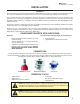
Installation and Service Manual SAFETY GROUNDING IN STRUCTIONS WARNING: Risk of electrical shock. Connect to a properly grounded outlet only. This appliance must be grounded. In the event of malfunction or breakdown, grounding provides a path of least resistance for electric current to reduce the risk of electric shock. This appliance is equipped with a cord having an equipment-grounding conductor and a grounding plug.
Installation and Service Manual INSTALLATION SURVEY Prior to installation, a location survey is highly recommended to assure there is sufficient room for the FlexTower on the counter, for the BIB rack in the back room, and room to route the beverage tubing from the BIB rack. If an ice drink dispenser heat exchanger is used, assure that the ice drink dispenser is in close proximity to the FlexTower area so the heat exchanger can be easily routed to the tower to provide cold water for the finished beverages.
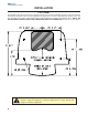
Installation and Service Manual INSTALLATION FOOTPRINT The FlexTower must be secured to the countertop using the four (4) holes provided in the base of the unit and using the hardware provided. Follow customer guidelines for placement of the unit or approximately 10 inches (25.4 cm) from the edge of the counter. A mounting template is provided which is printed on the shipping carton. NOTE: DO NOT DISCARD SHIPPING CARTON UNTIL MOUNTING TEMPLATE IS REMOVED. Also see the Footprint below.
Installation and Service Manual INSTALLATION INSTALLATION PROCEDURE • • • • • Assure that 16 bags of syrup are available at location. Coordinate this with the store manager. Manitowoc Beverage Equipment does not supply syrup. Carefully unpack FlexTower and inspect for damage. If damage is noted, file freight claim with carrier. Remove mounting template from shipping carton for use in positioning FlexTower on counter and drilling holes for mounting.
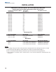
Installation and Service Manual INSTALLATION PRECHILL COIL RETROFIT KIT & ACCESSORY MATRIX Cooling Coil and Left Side Replacement Strip Lid Panel Kits Ice Beverage Dispenser Model (See Note 1) Strip Lid Kit (See Note 1) Part Number For Kit MDH-302 MDH-302 MDH-302 MDH-302 MDH-302 MDH-302 MDH-402 MDH-402 MDH-402 MDH-402 MDH-402 MDH-402 MDH-402 MDH-402 IB4 IB5 SL3 SL4 SL7 SL11 SL5 SL6 SL9 IB6 IB7 IB8 IB9 SL8 020001176 020001176 020001177 020001178 020001179 020001180 020001246 020001247 020001248 0200012
Installation and Service Manual INSTALLATION PRECHILL COIL RETROFIT KIT 1A 1A 2A 2B 1B FIGURE 1 3F 3B 3G 3E 3E 3C 3A 3D FIGURE 2 3.00 inches 4C 4A 4D 4B 1. Disconnect or shut of power, water supply to ice maker or makers (1A) and power supply to ice beverage dispenser (1B) (See Figure 1). Failure to do so may cause electrical shock or injury. 2.
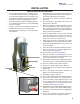
Installation and Service Manual INSTALLATION PRECHILL COIL RETROFIT KIT 6A 5B 5C 5A FIGURE 4 7A 7E 7B 7D 7C FIGURE 5 8D 8E 8C 8A 8B FIGURE 6 12 7. Place the cooling coil heat exchanger (5A) into the previously cleared and cleaned ice storage bin (5B) as shown (See Figure 4). Be sure the coil is resting flat on coldplate (5C) of the ice beverage dispenser (See Figure 5). The inlet and outlet fittings (8E) of the cooling coil heat exchanger will exit over previously trimmed 3.
Installation and Service Manual INSTALLATION RECIRCULATION LINES AND PUMP PARTS INCLUDED IN KIT NO: 020000783 Qty. 1 3 1 10 6ft Description Part Number Recirculation pump/w/fittings Line insulated beverage Instructions Recirculation lines Clamp Otiker 15.7 Tape Cork Insulation 020000780 020000781 020000782 15.7-706R RM051120 1B 1C 1F 1E 1D 1G 1A FIGURE 1 2B FIGURE 2 3A 3B 2A 1. If required secure recirculation pump (1A) to counter or under counter that unit is installed on (See Figure 1).
Installation and Service Manual INSTALLATION RECIRCULATION LINES AND PUMP 4C 7. Chiller Installations: Route insulated beverage line from the coil outlet (5C) up through either the back or bottom of tower (4A) as shown (See Figures 4 and 5). Route insulated beverage line through left side hole in the valve mount plate (4B) as shown (See Figure 4). Connect insulated beverage line to left side of barb fitting (4C) and secure line to barbed fitting with otiker clamp (See Figure 4).
Installation and Service Manual INSTALLATION DRAINAGE OPTIONS The drains for FLEXTOWER connect to the drain pan Option One Option Two Drainage through the bottom of the unit: Drainage through the back of the unit: Straight Fitting Radiator Clamp 90° Elbow Fitting Flexble Tubing Radiator Clamp Flexble Tubing Back of unit Openings for beverage and drain lines.
Installation and Service Manual INSTALLATION BRIXING PROCEDURE NOTE: This procedure is for flavors requiring 5:1 water to syrup ratio. Control Board Program Button LED Water Valve Syrup Injection Shroud OZ C C C C OZ 225 8 200 7 175 6 45 150 5 125 4.75 1 30 25 20 15 11:1 11:1 Touchpad Selection Areas 100 4 3 75 2 50 50 1 5:1 40 35 10 5 5:1 R ATIO R ATIO Funnel and 5:1 Brix Cup 1.
Installation and Service Manual INSTALLATION FLEXTOWER WATER RECIRCULATION PUMP FLOW FLEXTOWER WATER CHILLER FLOW Plumbing and Wiring Diagrams can be located inside the front cover of the FlexTower.
Installation and Service Manual INSTALLATION FT-8 PLUMBING DIAGRAM FT-12 PLUMBING DIAGRAM Plumbing and Wiring Diagrams can be located inside the front cover of the FlexTower.
Installation and Service Manual INSTALLATION FT-16 PLUMBING DIAGRAM Plumbing and Wiring Diagrams can be located inside the front cover of the FlexTower.
Installation and Service Manual OPERATION BASIC FUNCTIONS The FlexTower is a free standing unit which is designed for counter top merchandising and dispensing of non carbonated finished beverages and flavoring syrups in any combination up to 16 flavors. Dispensing is accomplished by supplying syrup to an electric valve via a BIB pump and routing the syrup to a common dispense point at an electric valve centrally located to supply plain water.
Installation and Service Manual OPERATION SPECIFICATIONS SERIAL PLATE Serial Plate Serial Plate 21
Installation and Service Manual OPERATION PROGRAMMING MODES LED Display Program Button CONTROL BOARD RUN OR DISPENSE MODE (Control Board LED Displays 0) For finished drink, press and hold any labeled finished drink touchpad area to manually dispense a finished noncarbonated drink (all touchpad areas are defaulted from factor to manual dispense mode).
Installation and Service Manual OPERATION PROGRAMMING MODES LED Display Program Button TIMED DISPENSE MODE (Flavor Adder Dispensed) Once in program mode (2), control board LED displays (2). Press any touchpad selection area three times in less than three seconds and selection area LED lights will blink three times to indicate the touchpad area has been programmed for timed dispense. Then the first and last touchpad selection areas will illuminate, which will allow increasing the timed dispense cycle by .
Installation and Service Manual OPERATION PROGRAMMING MODES 8 Section Area Touchpad TOUCHPAD CONFIGURATION MODE Once in program mode (5), control board LED displays (5). Press the first and last touchpad selection areas on both touchpads. The touchpad LED lights sequence through all the touchpad selection areas indicating the touchpad has been configured. After configuring both touchpads either enter another program mode or exit the programming modes, which will save programming mode changes.
Installation and Service Manual USER MAINTENANCE PREVENTATIVE MAINTENANCE NOTICE: Under normal operating conditions, periodic cleaning is minimal but absolutely necessary. Preventative maintenance is a vital part of keeping your FlexTower in top condition. Following the guidelines below will assist you in continued trouble free operation of your unit. Contact MBE at 1-800-367-4233 for more information about our ProActive Maintenance Program. 1. Conduct daily maintenance of the machine. 3.
Installation and Service Manual USER MAINTENANCE DAILY CLEANING Cleaning the grid, splash shield and drain pan Splash Shield Switch 1. Turn off the on/off rocker switch located on left side of the unit. 2. Lift the grid and splash shield to remove them from the drain pan. 3. Using mild soap, warm water and a clean cloth, wipe the drain pan. Then, rinse with clean, warm water.
Installation and Service Manual USER MAINTENANCE BEVERAGE SYSTEM CLEANING NOTICE: When changing syrup boxes, immerse connector in warm water (100° F, 38° C - maximum temperature) to remove syrup residue. • RECOMMENDED SANITATION INTERVAL IS EVERY 90 DAYS Sanitize the beverage system at initial start-up as well as regularly scheduled cleaning. The drain pan must be in place under soda valves, to carry away detergent and sanitizing agents that will be flushed through valves.
Installation and Service Manual USER MAINTENANCE BAG-IN-BOX SYSTEM 11. Draw sanitizing solution through system until solution is dispensed. 12. Repeat step 11 until all syrup circuits contain sanitizer solution. 13. Allow sanitizer solution to remain in system for 15 minutes. 14. Remove cosmetic nozzle and the water valve nozzlediffuser assembly. 15. Scrub water valve nozzle-diffuser assembly, the cosmetic nozzle and the inside of the syrup shroud assembly with a soft cloth and the detergent solution. 16.
Installation and Service Manual EXPLODED VIEWS, PARTS & DIAGRAMS FT-8 WIRING DIAGRAM Plumbing and Wiring Diagrams can be located inside the front cover of the FlexTower 29
Installation and Service Manual EXPLODED VIEWS, PARTS & DIAGRAMS FT-12 WIRING DIAGRAM Plumbing and Wiring Diagrams can be located inside the front cover of the FlexTower 30
Installation and Service Manual EXPLODED VIEWS, PARTS & DIAGRAMS FT-16 WIRING DIAGRAM Plumbing and Wiring Diagrams can be located inside the front cover of the FlexTower 31
Installation and Service Manual EXPLODED VIEWS, PARTS & DIAGRAMS POWER SUPPLY WIRING 32
Installation and Service Manual EXPLODED VIEWS, PARTS & DIAGRAMS POWER SUPPLY No Part Number Description 1 2 3 4 5 6 7 8 9 10 11 12 13 14 15 SCREW 6-32X3/8" SS PH RHMS WASHER STAR #8 SS TIP 1/8IN TINY PLASTIC CLIP PLASTIC WIRE & CORD PLUG HEYCO CORD STRAIN RELIEF COVER BOX ELECTRICAL BASE ELECRICAL BOX TRANSFORMER 75VA 120V w/BREAKER CORD ELECTRIC SCR 8-32 X 1/2 GRND ZINC SCREW 8-32 X 1/2 LABEL WARNING LABEL WIRING HARNESS 120 VOLT SUPPLY LABEL GROUND 0900904 0901915 0904504 0905403 1200301 4340006 500
Installation and Service Manual EXPLODED VIEWS, PARTS & DIAGRAMS FLEXTOWER EXPLODED VIEW 34
Installation and Service Manual EXPLODED VIEWS, PARTS & DIAGRAMS FLEXTOWER PARTS LIST No. Part Number Description No. Part Number Description 1 2 3 4 5 6 7 8 9 10 11 12 13 14 15 16 17 18 19 20 21 FLOMATIC VALVE BLOCK .
Installation and Service Manual TROUBLESHOOTING C O N D IT IO N IN V E S T IG AT IO N CHECK C O R R E C T IO N N o p o w e r a t unit.
INDEX B F P T brixing ....................................... 2 FOREWORD ............................ 2 Parts 29, 30, 31, 32, 33, 34, 35 TROUBLESHOOTING ............ 36 C G Q U Grid ......................................... 25 Qualified Service Personnel ..... 5 UNPACKING ............................. 2 I R W INSPECTION ............................ 2 Installation Date ........................ 2 irregularities .............................. 2 Relocation .................................
Manitowoc Beverage Equipment 2100 Future Drive Sellersburg, IN 47172-1868 Tel: 812.246.7000, 800.367.4233 Fax: 812.246.9922 www.manitowocbeverage.com In accordance with our policy of continuous product development and improvement, this information is subject to change at any time without notice.