MD/MDH SERIES MD 150/175/200/250 & MDH 302/402 Beverage/Ice Dispensers INSTALLATION & SERVICE GUIDE Part Number 5010330 Manitowoc Beverage Equipment 2100 Future Drive Sellersburg, IN 47172-1868 Tel: 812.246.7000, 800.367.4233 Fax: 812.246.9922 www.manitowocbeverage.com In accordance with our policy of continuous product development and improvement, this information is subject to change at any time without notice.
FOREWORD Manitowoc Beverage Equipment (MBE) developed this manual as a reference guide for the owner/ operator, service agent, and installer of this equipment. Please read this manual before installation or operation of the machine. A qualified service technician should perform installation and startup of this equipment, consult the Troubleshooting Guide within this manual for service assistance. If you cannot correct the service problem, call your MBE Service Agent or Distributor.
TABLE OF CONTENTS FOREWORD ........................................................................................................ 2 UNPACKING AND INSPECTION ........................................................................ 2 WARRANTY INFORMATION ............................................................................... 2 SAFETY ............................................................................................................... 6 IMPORTANT SAFETY INSTRUCTIONS ........................
TABLE OF CONTENTS OPERATION ...................................................................................................... 23 UNIT INSPECTION ........................................................................................................... 23 ICE STORAGE AND DISPENSING ................................................................................... 23 ROCKING CHUTE ICE DISPENSING ................................................................................
Installation and Service Manual TABLE OF CONTENTS EXPLODED VIEWS, PARTS & DIAGRAMS ..................................................... 42 MD 150/175/200/250 EXPLODED VIEW ............................................................................ 42 MD 150 PARTS LIST ....................................................................................................... 43 MD 175 PARTS LIST .......................................................................................................
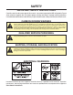
SAFETY IMPORTANT SAFETY INSTRUCTIONS Carefully read all safety messages in this manual. Learn how to operate the MD unit properly. Do not allow anyone to operate the unit without proper training and keep it in proper working condition. Unauthorized modifications to the MD may impair function and/or safety and affect the life of the unit. CARBON DIOXIDE WARNING DANGER: Carbon Dioxide (CO2) displaces oxygen.
Installation and Service Manual SAFETY GROUNDING IN STRUCTIONS WARNING: Risk of electrical shock. Connect to a properly grounded outlet only. This appliance must be grounded. In the event of malfunction or breakdown, grounding provides a path of least resistance for electric current to reduce the risk of electric shock. This appliance is equipped with a cord having an equipment-grounding conductor and a grounding plug.
INSTALLATION PRE-INSTALLATION CHECK LIST When installing any system, first make sure the major components are available. Generally the major components necessary for an installation are: Do you have enough space to install the dis Pre-mix system: Is the countertop level? penser or a dispenser and top mounted cuber? Does the top mounted cuber (if utilized) have a minimum of 6 inches (15.
Installation and Service Manual INSTALLATION UNIT INSTALLATION 1. Place the dispenser in the desired location. tween those pressures proper measures must be taken to regulate them to correct settings. 2. Run the beverage lines and water lines (make sure to install the water connections to the proper inlets. Connection “A” comes from the procon pump and is your carbonated water supply and Connection “B” is your plain water supply. (Refer to plumbing diagrams.) 6. Turn CO2 supply on to the dispenser.
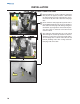
INSTALLATION CARB TANK PURGE TUBE ROUTING 1. During installation of unit the carbonator tank purge tube (A) must be properly routed to a drain. Once the splash panel has been removed from unit remove twist tie (B) that holds carbonator tank purge tube. A 2. Route carbonator tank purge tube (A) down front of unit and behind drain pan. Be sure not to collapse or kink carbonator tank purge tube during routing from unit to drain.
Installation and Service Manual INSTALLATION COLD CARB AND AMBIENT SYSTEM PRESSURES 1. Incoming tap water should be at a minimum pressure of 40 psi and a maximum of 55psi. 2. BIB pressure gauge set for 60 psi. 3. Carbonator Pressure gauge: • Cold Carbonation set for 75 psi. • Ambient systems should be set at 90 psi to 100 psi. NOTE: If incoming water pressure is under 40 psi, a water booster is recommended. If incoming water pressure is over 55 psi, a water regulating valve is required.
INSTALLATION COLD CARB BAG-IN-BOX (B-I-B) SYSTEM 12
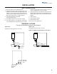
Installation and Service Manual INSTALLATION TOP MOUNTED ICEMAKER REQUIREMENTS 1 2 3 Location - Avoid placing the dispenser and/or ice machine near heat sources such as radiators, ovens, refrigeration equipment and direct sunlight. Clearances - Six inch (15.2 cm) clearance on all sides of the icemaker is needed. Front of icemaker to be flush with front of dispenser- The front of the icemaker should be flush with the front of the dispenser, as shown in the draw1 2 4 5 ing above.
INSTALLATION BAFFLE FOR MANITOWOC™ CUBERS When installing a Manitowoc™ “S” series Ice Machine on a Servend MD-series dispenser, a baffle kit is required for proper installation. The baffle kit is designed to prevent ice from lying against the front of the ice machine, and melting down the front of the dispenser. There are two different baffle kits available from Servend. One kit is for the 30" wide “S” series ice machine, and the other kit is for the 22" wide “S” series ice machine.
Installation and Service Manual INSTALLATION PLUMBING DIAGRAM LOCATION The plumbing diagram is printed on a white vinyl label, usually located above the inlet tubes for syrup and later. The plumbing diagram label can be accessed by removing the splash panel of the dispenser. The plumbing diagram label explains which inlet coldplate fittings supply which dispenser valves and water manifolds.
INSTALLATION MD-150 6 VALVE PLUMBING DIAGRAM MD-150 6 VALVE FLEX MANIFOLD 16
Installation and Service Manual INSTALLATION MD-175 8 VALVE PLUMBING DIAGRAM MD-175 8 VALVE FLEX MANIFOLD 17
INSTALLATION MD-200/250 8 VALVE PLUMBING DIAGRAM MD-200/250 8 VALVE FLEX MANIFOLD 18
Installation and Service Manual INSTALLATION MD-200/250 10 VALVE PLUMBING DIAGRAM MD-200/250 10 VALVE FLEX MANIFOLD 19
INSTALLATION MD-302 12 VALVE PLUMBING DIAGRAM LEFT RIGHT MD-302 12 VALVE FLEX MANIFOLD (1 PER SIDE) 20
Installation and Service Manual INSTALLATION MD-402 16 VALVE PLUMBING DIAGRAMS LEFT RIGHT MD-402 16 VALVE FLEX MANIFOLD (1 PER SIDE) 21
INSTALLATION MD-402 20 VALVE PLUMBING DIAGRAMS LEFT RIGHT MD-402 20 VALVE FLEX MANIFOLD (1 PER SIDE) 22
Installation and Service Manual OPERATION UNIT INSPECTION Thoroughly inspect the unit upon delivery. Immediately report any damage that occurred during transportation to the delivery carrier. Request a written inspection report from a claims inspector to document any necessary claim. ICE STORAGE AND DISPENSING Servend dispensers are designed to dispense hard, cube ice up to one-inch square. The ice shapes and sizes listed below are recommended for dispensing.
OPERATION AUTO BAG SELECTORS These are used on higher volume B-I-B systems where two or more bags of the same product are connected to one pump and one system. An auto bag selector is essentially a valve that automatically changes from one bag (or series of bags) to another bag (or series of bags) of syrup as the bags empty, allowing a constant flow of product. B-I-B The Bag-In-Box system refers to a plastic disposable bag.
Installation and Service Manual OPERATION BACK ROOM PACKAGE BAG-IN-BOX SYSTEM Creating Carbonated Water: 1. Incoming tap water - should be at a minimum dynamic pressure of 40 psi and maximum static pressure of 55 psi. 2. Carbonator Water pump motor - Powers the water pump. The water pump motor is part of the carbonator pump deck. 3. Carbonator Water pump - Pumps tap water into the carbonator tank. The water pump is part of the carbonator.
OPERATION FIGAL SYSTEM 1. CO2 cylinder - Holds highly pressurized carbon dioxide (CO2 ). The CO2 cylinder is a steel or aluminum cylinder tank. CO2 gas flows to the primary pressure regulator. 2. Primary pressure regulator - Lowers the CO2 gas pressure, usually to 100 psi. 3. Lowered outgoing pressure gauge - Gauge indicates lowered outgoing pressure from the CO2 cylinder after being routed through the primary pressure regulator.
Installation and Service Manual OPERATION CARBONATION The purpose of the carbonator is to take water and combine it with CO2 to create carbonated water. Tap water at street water pressure (minimum 40 PSI dynamic or flowing pressure in a 1/2" water line) must be forced into a tank that contains CO2 (usually at 100 PSI) by using a pump to raise the water pressure above the CO2 pressure. CO2 is absorbed into the water as the water passes through the gas.
OPERATION MD SERIES COUNTERTOP MEASUREMENTS Letter Description MD-150 MD-175 MD-200/250 MD-250-36 A Unit Width 22” 24” 30” 36" B Unit Depth 30 1/2" 30 1/2" 30 1/2" 30 1/2" C Outside Ice Bin Depth 22" 22 1/2" 22 1/2" 22 1/2" D Under Unit Width 18" 20" 26" 32" E Under Unit Depth 20 1/2" 20 1/2" 20 1/2" 20 1/2" F Recommended countertop Cut-out* 3"x13" 3"x14" 3"x18" 3"x18" G Maximum Countertop Cut-out* 18"x20 1/2" 20"x20 1/2" 26"x20 1/2" 32"x20 1/2" CAUTION: *Cut
Installation and Service Manual OPERATION MD SERIES SPECIFICATIONS MD Series dispensers have a stainless steel cabinet and lighted merchandiser standard. Beverage valves, coldplate connections, drain connections and electrical components are front serviceable. MD Series dispensers drain through a single 3/4" NPT connection to the drain pan. The standard voltage for MD Series dispensers is 120VAC-60Hz. A power cord is provided with 120VAC-60Hz models only.
OPERATION MDH SERIES COUNTERTOP MEASUREMENTS Letter Description MDH-302 MDH-402 A Unit Width 42 ¾" 60" B Unit Depth 30 ½ " 30 ½" C Outside Ice Bin Depth 22 ½" 22 ½" D Under Unit Width 38 ¾" 56 ½" E Under Unit Depth 20 ½" 21 ¼" F Recommended Countertop Cut-out* 3" X 32" 3" X 48" G Maximum Countertop Cut-out* 38 ¾" X 20 ½" 56 ½" X 21 ¼" CAUTION: *Cutting the countertop may decrease its strength.
Installation and Service Manual OPERATION MDH SERIES SPECIFICATIONS MDH Series dispensers have a stainless steel cabinet and lighted merchandiser standard. Beverage valves, coldplate connections, drain connections and electrical components are front serviceable. MDH Series dispensers drain through a two 3/4" NPT connection to the drain pan. The standard voltage for MDH Series dispensers is 120VAC60Hz. A power cord is provided with 120VAC-60Hz models only.
OPERATION ROCKING CHUTE ICE DELIVERY SWITCH ADJUSTMENT 32 1 To properly adjust the switch, first unplug the power cord to the unit then remove the merchandiser. This will give you access to the ice delivery switch located on the left side of the rocking chute. 2 Begin by observing the chute by slowly pushing against the rocking chute. When the ice delivery switch clicks, measure the distance from the door stops on the rocking chute bracket to the door.
Installation and Service Manual OPERATION SETTING THE AUTOMATIC AGITATION TIMER Some MD Series ice / beverage dispensers have an optional timer, which agitates ice stored in the dispenser bin. The timer is preset at the factory for three seconds ice agitation every three and one half hours. Beginning July, 1999 this timer is not adjustable. To reset the older style timer, use the following procedure: 1. Place a small screwdriver in the adjustment pot marked “ON” (See illustration at right). 2.
OPERATION SEQUENCE OF OPERATION Manufactured before early 1994 Manufactured beginning early 1994 Pulley Microswitc Solenoid/Door Mount Door Bumper Plunger Cable Door Solenoid F SH PU IC OR E Customer’s cup presses rocking chute push lever or customer’s hand presses push button. The clear plastic arm at the top and the left rear of the clear plastic chute pushes upward on the door. Customer’s cup presses against the push plate.
Installation and Service Manual USER MAINTENANCE PREVENTATIVE MAINTENANCE Preventative maintenance is a vital part of keeping your Servend dispenser in top condition. Following the guidelines below will assist you in continued trouble free operation of your unit. Contact MBE at 1-800-367-4233 for more information about our ProActive Maintenance Program. 1. Conduct daily maintenance of the machine. Possible excess ice storage reasons: 2. Perform monthly maintenance of the machine.
USER MAINTENANCE HOW TO DISASSEMBLE FOR CLEANING OR MAINTENANCE 8 10 Agitator arm and paddle wheel pin: 8. Rotate the agitator arm so the paddle wheel pin handle is pointing up, toward the ceiling. For the MD-302 dispenser only, reach inside the bin through the area where the strip lid has been removed. 9. Loosen the hand-removable paddle wheel pin from the agitator by twisting counter clockwise until it snaps from the agitator bar... 10. Then remove the paddle wheel pin from the hole in the agitator.
Installation and Service Manual USER MAINTENANCE HOW TO DISASSEMBLE FOR CLEANING OR MAINTENANCE Disassemble the rocking chute: 1. Loosen the two knurled fasteners that hold the merchandiser in place. 2. Remove the merchandiser. 3. Remove outer bracket. 4. Remove door lock. 5. Remove door. 6. Remove ice chute. 7. Model MD-302 has two rocking chutes. Remove both rocking chutes using the same procedure above. Disassemble the solenoid style chute: 1.
USER MAINTENANCE DAILY CLEANING All cleaning must meet your local health department regulations. The following cleaning instructions are provided as a guide. CAUTION: Use only warm soapy water to clean the exterior of the tower. Do not use solvents or other cleaning agents. Do not pour hot coffee into the drain pan. Pouring hot coffee down the drain pan can eventually crack the drain pan, especially if the drain pan is cold or still contains ice. Clean the exterior and drain pan: 1.
Installation and Service Manual USER MAINTENANCE MONTHLY CLEANING Clean and sanitize the ice bin and cold plate: 1. Unplug unit and remove all ice from the ice bin. 2. Mix a solution of mild detergent to clean the dispenser bin and components. 3. Wash the ice bin using a sponge and the mild detergent solution. 4.
USER MAINTENANCE BEVERAGE SYSTEM CLEANING Sanitize the beverage system at initial start-up as well as regularly scheduled cleaning. The drain pan must be in place under soda valves, to carry away detergent and sanitizing agents that will be flushed through valves. BAG-IN-BOX SYSTEM The procedure below is for the sanitation of one syrup circuit at a time. Repeat to sanitize additional circuits.
Installation and Service Manual USER MAINTENANCE BAG-IN-BOX SYSTEM 10. Connect Bucket 3 to system. 11. Draw sanitizing solution through system until solution is dispensed. 12. Repeat step 11 until all syrup circuits contain sanitizer solution. 13. Allow sanitizer solution to remain in system for 15 minutes. 14. Remove nozzles and diffusers from beverage valves. 15.
EXPLODED VIEWS, PARTS & DIAGRAMS MD 150/175/200/250 EXPLODED VIEW 42
Installation and Service Manual EXPLODED VIEWS, PARTS & DIAGRAMS MD 150 PARTS LIST MD 175 PARTS LIST 43
EXPLODED VIEWS, PARTS & DIAGRAMS MD 200/250 PARTS LIST 44
Installation and Service Manual EXPLODED VIEWS, PARTS & DIAGRAMS MDH 302/402 EXPLODED VIEW 45
EXPLODED VIEWS, PARTS & DIAGRAMS MDH 302 PARTS LIST MDH 402 PARTS LIST 46
Installation and Service Manual EXPLODED VIEWS, PARTS & DIAGRAMS MD 150 115V PRE-MIX WIRING DIAGRAM CAUTION ELECTRICAL SHOCK HAZARD DISCONNECT POWER BEFORE SERVICING MERCHANDISING LAMP (250) BLACK OPTIONAL THERMOSTAT MERCHANDISING LAMP IN BLACK PURPLE ORANGE OUT WHITE LIGHT STARTER BALLAST BLACK BLACK BALLAST 5 1 OPTIONAL AUDIBLE ALARM BLUE 3 BLUE WHITE GRAY 4 2 RED YELLOW OPTIONAL AGITATION TIMER BUZZER 3 2 1 WHITE TIMER PURPLE BLACK BLACK ORANGE WHITE WHITE LIGHT STARTER G O
EXPLODED VIEWS, PARTS & DIAGRAMS MD 150/175/200 115V WIRING DIAGRAM TO RESET TRANSFORMER: CAUTION (115 VOLT UNITS ONLY) 1. DISCONNECT POWER SUPPLY. 2. PRESS RESET BREAKER SWITCH ON TRANSFORMER. 3. REPLACE MERCHANDISER (FRONT ENCLOSURE). 4. RECONNECT POWER SUPPLY.
Installation and Service Manual EXPLODED VIEWS, PARTS & DIAGRAMS MD 150 220V PRE-MIX WIRING DIAGRAM CAUTION ELECTRICAL SHOCK HAZARD DISCONNECT POWER BEFORE SERVICING MERCHANDISING LAMP (250) BLACK OPTIONAL THERMOSTAT MERCHANDISING LAMP IN BLACK PURPLE ORANGE OUT WHITE OPTIONAL AGITATION TIMER LIGHT STARTER BALLAST BLACK BLACK 5 1 WHITE OPTIONAL AUDIBLE ALARM BLUE 3 BLUE GRAY 4 2 BALLAST RED GREEN YELLOW G BUZZER 3 2 1 BLACK BLACK BROWN ORANGE PURPLE WHITE WHITE LIGHT STARTER
EXPLODED VIEWS, PARTS & DIAGRAMS MD 150/175/200 220V WIRING DIAGRAM CAUTION 220/240 VOLT ELECTRICAL SHOCK HAZARD DISCONNECT POWER BEFORE SERVICING WHITE RED MERCHANDISING LAMP PURPLE BLACK OPTIONAL THERMOSTAT BALLAST BLACK OUT WHITE BLACK BLACK LINE LOAD LOAD N L1 LINE OPTIONAL AUDIBLE ALARM BLUE 2 1 TIMER WHITE WHITE BLUE NO YELLOW NC WHITE BLUE ICE DISPENSE SWITCH OPTIONAL BLACK ORANG COMMON E OPTIONAL EMPTY LIGHT BLACK VALVE KEYSWITCH BUZZER 3 BLACK BLUE RED BLUE PURPLE
Installation and Service Manual EXPLODED VIEWS, PARTS & DIAGRAMS MD 250 115V WIRING DIAGRAM TO RESET TRANSFORMER: CAUTION (115 VOLT UNITS ONLY) 1. DISCONNECT POWER SUPPLY. 2. PRESS RESET BREAKER SWITCH ON TRANSFORMER. 3. REPLACE MERCHANDISER (FRONT ENCLOSURE). 4. RECONNECT POWER SUPPLY.
EXPLODED VIEWS, PARTS & DIAGRAMS MD 250 220V WIRING DIAGRAM CAUTION 220/240 VOLT ELECTRICAL SHOCK HAZARD DISCONNECT POWER BEFORE SERVICING WHITE RED OPTIONAL MERCHANDISING LAMP BLACK PURPLE OPTIONAL MERCHANDISING LAMP PURPLE BLACK OPTIONAL AGITATION TIMER G 4 2 WHITE OPTIONAL THERMOSTAT IN BLACK YELLOW RED BLACK BALLAST BLUE BALLAST BLACK ORANGE BLACK OUT PURPLE LINE 1 WHITE WHITE LOAD BLUE BLACK WHITE LOAD BLACK LINE BLUE WHITE 5 OPTIONAL AUDIBLE ALARM BLUE BLACK PURPLE G
Installation and Service Manual EXPLODED VIEWS, PARTS & DIAGRAMS MDH 302 115V WIRING DIAGRAM TO RESET TRANSFORMER: CAUTION (115 VOLT UNITS ONLY) 1. DISCONNECT POWER SUPPLY. 2. PRESS RESET BREAKER SWITCH ON TRANSFORMER. 3. REPLACE MERCHANDISER (FRONT ENCLOSURE). 4. RECONNECT POWER SUPPLY.
EXPLODED VIEWS, PARTS & DIAGRAMS MDH 302 220V WIRING HARNESS CAUTION 220/240 VOLT ELECTRICAL SHOCK HAZARD DISCONNECT POWER BEFORE SERVICING OPTIONAL MERCHANDISING LAMP BLUE BLUE BALLAST ICE DISPENSE SWITCH BLACK BLACK BLACK 5 LOAD 1 LOAD LOAD WHITE WHITE WHITE LINE WHITE BLACK BROWN LINE OPTIONAL AUDIBLE ALARM BLUE LOAD LINE BLACK TRANSFORMER 3 GRAY 4 LINE BLUE BLUE WHITE YELLOW 2 OUT YELLOW OPTIONAL AGITATION TIMER BLACK ICE DISPENSE SWITCH NO NC IN BLUE ORANGE NO NC
Installation and Service Manual EXPLODED VIEWS, PARTS & DIAGRAMS MDH 402 115V WIRING DIAGRAM 55
EXPLODED VIEWS, PARTS & DIAGRAMS MDH 402 220V WIRING DIAGRAM TO RESET TRANSFORMER: CAUTION (115 VOLT UNITS ONLY) MDH-402 1. DISCONNECT POWER SUPPLY. 2. PRESS RESET BREAKER SWITCH ON TRANSFORMER. 3. REPLACE MERCHANDISER (FRONT ENCLOSURE). 4. RECONNECT POWER SUPPLY. ELECTRICAL SHOCK HAZARD DISCONNECT POWER BEFORE SERVICING DWG#: 5029432 REV.
Installation and Service Manual TROUBLESHOOTING PUMP PROBLEM POSSIBLE CAUSE CORRECTIVE ACTION Black and/or red probe shorted Remove probes and bend straight or replace with new probe(s) Problem with motor or motor wiring Check line voltage first. Check AC voltage across load terminals on Liquid Level Control. If voltage is 120 plus or minus 10%, replace motor or motor wiring. Problem with Liquid Level Control Board. Check line voltage first.
TROUBLESHOOTING PUMP PROBLEM POSSIBLE CAUSE CORRECTIVE ACTION Pump motor intermittent Problem with Liquid Level Control Board. Check line voltage first. If AC voltage across load terminals on Liquid Level Control Board is not 120 plus or minus 10%, replace the Liquid Level Contorl board. Pump motor starts and stops, short cycles, as soon as water level drops below Red (High) probe. Black (Low) Lead wire is open or disconnected.
Installation and Service Manual TROUBLESHOOTING DRINKS CONDITION Water only dispensing Syrup and CO2 only dispensing INVESTIGATION No pressure Carbonator CHECK CORRECTION Regulator(s) out of adjustment Check/adjust regulator(s) Out of CO2 Install fresh tank Defective regulator(s) Check/repair/replace regulator(s) CO2 line pinched, kinked or obstructed Check/repair/replace CO2 line No power Check power supply. Plug in carbonator or reset breaker.
Installation and Service Manual TROUBLESHOOTING LIQUID LEVEL CONTROL START Does Pump motor come on? Yes No Remove red and black wires from LLC. Yes Is pump motor operation intermittent ? No Black and/or red probe shorted. Remove probes, straighten or replace if necessary. Yes Does pump motor come on? Short H and C terminals on LLC. No Measure AC voltage across load terminals on LLC. Does the pump motor shut off? No Check pump motor and wiring.
Installation and Service Manual
INDEX B F O T Back Room Package ............... 25 brixing ....................................... 2 FOREWORD .............................. 2 Operation .................................. 6 TROUBLESHOOTING 57, 58, 59, 60 H P health department ................... 38 Power outlet ............................. 8 I Q C Carbon Dioxide ......................... 6 CAUTION .............. 9, 28, 31, 39 claims ...................................... 23 Cleaning ....................................
Manitowoc Beverage Equipment 2100 Future Drive Sellersburg, IN 47172-1868 Tel: 812.246.7000, 800.367.4233 Fax: 812.246.9922 www.manitowocbeverage.com In accordance with our policy of continuous product development and improvement, this information is subject to change at any time without notice.