Server Technology Solutions for the Data Center Equipment Cabinet Sentry Remote Power Manager - PT22 Installation and Operations Manual © 2005 Server Technology, Inc.
Instructions This symbol is intended to alert the user to the presence of important operating and maintenance (servicing) instructions in the literature accompanying the appliance. Dangerous Voltage This symbol is intended to alert the user to the presence of un-insulated dangerous voltage within the product’s enclosure that may be of sufficient magnitude to constitute a risk of electric shock to persons.
Table of Contents CHAPTER 1: INTRODUCTION 4 Quick Start Guide.............................................................................................................................4 Technical Support ............................................................................................................................4 Equipment Overview........................................................................................................................
Chapter 1: Introduction Quick Start Guide The following instructions will help you quickly install and configure your PT22 for use in your data center equipment cabinet. For detailed information on each step, go to the page number listed to the right. 1. 2. 3. 4. 5. 6. 7. Mount the PT22..........................................................................................................................6 Connect to the power source .......................................................................
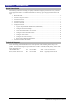
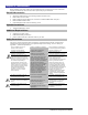
Equipment Overview 1. 2. 3. The power inlet/cord(s) connects the CDU to the electrical power source. Two RJ45 connectors for Serial (RS-232) and Ethernet connection. Two mini RJ11 connectors for Temperature/Humidity sensors. A number is printed above each PT22 outlet. These numbers may be used in commands that require an outlet name. 3 2 1 1 1 1 Figure 1.
Chapter 2: Installation Before installing your Sentry PT22, refer to the following lists to ensure that you have all the items shipped with the unit as well as all other items required for proper installation.
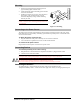
Mounting 1. 2. 3. Select the appropriate bracket mounting points for proper mounting depth within the rack. Attach the brackets to these mounting points with two screws for each bracket. Install the enclosure into your rack, using the slots in each bracket. The slots allow about ¼ inch of horizontal adaptability to align with the mounting holes of your rack. NOTE: A mounting bracket kit for 23” wide racks or cabinets is available. Contact your Server Technology Sales Representative for more information.
Connecting to the Unit Serial (RS232) port The PT22 is equipped with an RJ45 Serial RS-232 port for attachment to a PC or networked terminal server using the supplied RJ45 to RJ45 crossover cable and RJ45 to DB9F serial port adapter as required. See Power Ratings in Appendix C: Technical Specifications for more information on the Serial RS-232 port. Ethernet port The PT22 is equipped with an RJ45 10/100Base-T Ethernet port for attachment to an existing network.
Chapter 3: Operations INTERFACES Outlet Naming and Grouping Usernames and Passwords 10 10 10 HTML INTERFACE Logging In Outlet Control Individual..............................................................................................................................12 Group....................................................................................................................................12 Environmental Monitoring Input Load .............................................................
Interfaces The PT22 has two interfaces: the HTML interface accessed via the HTTP enabled Ethernet connections and the command line for serial and Telnet connections. Outlet Naming and Grouping For commands requiring an outlet name, you may specify it in one of two ways: a predefined absolute name or a descriptive name assigned by an administrator. For units with multiple infeed connectors, absolute names are specified by a period (.) followed by the tower letter, the infeed letter and outlet number.
HTML Interface The HTML interface is constructed of three major components: the System Location bar, the User/Navigation bar and the Control Screen. The System Location bar displays the Sentry’s location and IP address as well as the current Control Screen title. The User/Navigation bar displays the current user and privilege level and provides access to all HTML pages. And the Control Screen is used to display current data and allow changes to outlet states or system configuration.
Outlet Control The Outlet Control section offers access to the Individual and Group outlet control pages. From the Individual and Group pages, the user can review and manipulate power control functions for all outlets and groups assigned to the current user. Both pages include the outlets absolute and descriptive names, the Outlet Status reported to the Sentry by the outlet, the current Control State being applied by the Sentry and the outlet load in amperes.
Environmental Monitoring Input Load The Input Load page displays the tower(s) absolute and descriptive name and the cumulative input load in amperes of all devices attached to the Sentry at the time the page was loaded. This page will refresh automatically every 10 seconds.
Network The Network configuration page is used for maintenance of the network interface. From this page an administrator may configure the IP address, subnet mask, gateway address, DNS addresses as well as view the link status, speed and duplex value. The Sentry is configured with the following network defaults to allow unit configuration out-of-the-box through either Telnet or HTML: • IP address: 192.168.1.254 • Subnet Mask: 255.255.255.0 • Gateway: 192.168.1.
Setting SSL access level Sentry SSL supports configuration of SSL connections as being either optional or required. The default access level is set to optional. • • Optional –Both non-secure (HTTP) and SSL encrypted connections (HTTPS) are allowed access. Required – ONLY SSL encrypted connections (HTTPS) are allowed access. Select Optional or Required from the Secure Access drop-down menu and press Apply. Serial Ports The Serial Ports configuration page is used for maintenance of all serial ports.
Editing modem initialization strings: Click on the Edit link in the Modem port Action column. On the subsequent Serial Port Edit page, enter the initialization string in the appropriate field and press Apply. The Init1 and Init2 strings may be up to 48 characters. The Attention and Hang-up strings may be up to 16 characters.
Adding and Deleting outlets from a group: Press the Edit link in the Action column for the associated group. On the subsequent Group Edit page, select or deselect outlets to be included in that group. Press Apply. Users The Users configuration page is used for creation and removal of usernames, assignment of accessible outlets and group, assignment of privilege levels and the changing of user passwords. Creating a new user: Enter a user name in the Username field.
Adding and Deleting serial port access: Click on the Ports link in the Access column for the associated user. On the subsequent User Ports page, select or deselect ports to be accessed by the user and press Apply. FTP The FTP configuration page is used for setup and maintenance of all settings required to perform an FTP firmware upload. See Appendix B: Uploading Firmware for more information on uploading firmware.
Configuring input feed traps: Click on the Input Feed Traps link. On the subsequent Input Feed Traps page, select or deselect the desired traps and press Apply. For Load traps, enter a maximum load value for the infeed in the High Load Threshold field and press Apply. The High Load Threshold value may be 0 to 255 (in amperes). Configuring outlet traps: Click on the Outlet Traps link. On the subsequent Outlet Traps page, select or deselect the desired traps and press Apply.
Configuring the authentication order: Select Remote -> Local or Remote Only from the drop-down menu and press Apply. For more information on remote authentication order, see Setting the authentication order on page 57. NOTE: Server Technology recommends NOT setting the authentication order to Remote Only until the LDAP has been fully configured and tested. Configuring LDAP groups: Click on the LDAP Groups link at the bottom of the page.
Configuring the authentication order: Select Remote -> Local or Remote Only from the drop-down menu and press Apply. For more information on remote authentication order, see Setting the authentication order on page 64. NOTE: Server Technology recommends NOT setting the authentication order to Remote Only until the LDAP has been fully configured and tested. Configuring TACACS+ privilege levels: Click on the TACACS+ Privilege Levels link at the bottom of the page.
Command Line Interface Logging In Logging in through Telnet requires directing the Telnet client to the configured IP address of the unit. Logging in through the Console (RS232) port requires the use of a terminal or terminal emulation software configured to support ANSI or VT100 and a supported data rate (300, 1200, 2400, 4800, 9600, 19200, 38400, 57600, or 115200 BPS) - 8 data bits-no parity-one stop bit and Device Ready output signal (DTR or DSR). To log in by RS-232 or Telnet: 1. Press Enter.
Administrative Command Summary (continued) Delete Portfromuser Removes access to one or all serial ports List User Displays all accessible outlets/groups/ports for a user List Users Displays privilege levels for all users Remove Group Deletes a group name Remove User Deletes a user account Restart Performs a warm boot Set DNS Sets the IP address of the Domain Name server Set FTP Filename Specifies the file to be uploaded via FTP Set FTP Filepath Specifies the filepath for the file to be upl
Operations Commands Operations commands manage outlet states, provide information about the Sentry environment and control session operations. Turning outlets on The On command turns on one or more outlets. When the command completes, a display indicating all outlets affected and their current states will be displayed. To turn outlets on: At the Sentry: prompt, type on, followed by an outlet name, and press Enter, or Type on, followed by a group name, and press Enter, or Type on all and press Enter.
Displaying outlet status The Status command displays the on/off status of one or more outlets. The command displays the status of only those outlets for which the current username has power control access. This display includes the outlet absolute and descriptive names, the Outlet State reported to the Sentry by the outlet and the current Control State being applied by the Sentry. If you do not specify any parameter with this command, the status of all accessible outlets is displayed.
Displaying accessible outlets The List Outlets command displays accessible outlets for the current user. The display includes the absolute and descriptive name of all outlets assigned to the current user. To display accessible outlets: At the Sentry: prompt, type list outlets and press Enter. Example The follow command displays all accessible outlets for the current user: Sentry: list outlets Outlet ID Outlet Name .A1 .
Displaying infeed status The Istat or Iload command displays the status of one or more infeed. This display includes the infeed absolute and descriptive names and the Input Status and current Load reported to the Sentry by the infeed. To display status of one or more infeeds: Type istat and press Enter, or Type iload and press Enter. Examples The following command displays the infeed status: Sentry: istat Input Feed ID Input Feed Name Input Status Input Load .AA .AB .AC .
Ending a session The Quit or Logout commands ends a session. A session ends automatically when no activity is detected for five minutes, or upon loss of connection. To end a session: At the Sentry: prompt, type quit and press Enter, or Type logout and press Enter. Administration Commands Administration commands may only be issued by a user with administrative privileges, such as the predefined Admn user or another user who has been granted administrative privileges with the Set User Admnpriv command.
Examples The following command changes the password for the user JohnDoe: Sentry: set user password johndoe Password: Verify Password: Setting user access level privileges The Set User Access command sets the access level privileges for a user. The Sentry has four defined access privilege levels; Admin, User, On-Only and View-Only. For more information on user access levels, see Changing a user’s access privilege level: on page 17.
Adding outlet access to a user The Add OutletToUser command grants a user access to one or all outlets. To grant access for more than one outlet, but not all outlets, you must use multiple Add OutletToUser commands. To grant outlet access to a user: At the Sentry: prompt, type add outlettouser, optionally followed by an outlet name and a username. Press Enter, or Type add outlettouser all, followed by a username and press Enter.
Deleting serial port access for a user The Delete PortFromUser command removes a user’s access to a serial port. You cannot remove access to any serial port for an administrative level user. To delete serial port access for a user: At the Sentry: prompt, type delete portfromuser, optionally followed by a Port name and a username. Press Enter. Displaying user outlet, group and serial port access The List User command displays all accessible outlets, groups and serial ports for a user.
Creating a descriptive outlet name The Set Outlet Name command assigns a descriptive name to an outlet. You may use this name in commands that require an outlet name as an alternative to using the outlet’s absolute name. To create an outlet name: At the Sentry: prompt, type set outlet name, followed by the absolute outlet name and a descriptive name of up to 24 alphanumeric and other typeable characters (ASCII 33 to 126 decimal - spaces are not allowed). Outlet names are not case sensitive. Press Enter.
Displaying outlet information The Show Outlets command displays information about all outlets. This information includes: • • • Sequencing and reboot timer values Descriptive outlet name, if applicable Outlet wakeup state setting To display outlet information: At the Sentry: prompt, type show outlets and press Enter. Example The following command displays all outlet information: Sentry: show outlets Outlet ID Outlet Name Wakeup State Post-On Delay (seconds) .A1 .B1 .C1 .
The following commands usese the outlets’ descriptive names to add outlets DataServer_1 and WebServer_1 to group name ServerGroup_1: Sentry:add OutletToGroup DataServer_1 ServerGroup_1 Sentry:add OutletToGroup WebServer_1 ServerGroup_1 The following command add all outlets to group name ServerGroup_1: Sentry: add OutletToGroup Outletname: all Groupname: ServerGroup_1 Deleting an outlet from a group The Delete OutletFromGroup command deletes an outlet from a group.
Setting the serial ports data-rate The Set Port Speed command sets the default data-rate for the serial port. Valid data-rates are 1200, 2400, 4800, 9600, 19200, 38400, 57600 and 115200. To set the serial port data-rate: At the Sentry: prompt, type set port speed, follow by the data-rate and press Enter.
Editing modem initialization strings The predefined modem initialization strings may be edited by an administrative user. The Init 1 and Init 2 strings may be up to 48 characters each and the Attention and Hang-up strings may be up to 16 characters. For more information on the predefined initialization strings, see Enabling or disabling modem initialization strings: on page 15.
System Administration Creating a location description The Set Location command specifies text that appears in the HTML control screen’s Location field. The text is also appended to a Welcome to banner that appears when a user successfully logs in serially or through a Telnet session. If you do not issue this command, or if you issue this command without specifying any text, the control screen ’s Location field will be blank and no Welcome to banner will be displayed.
Displaying tower information The Show Towers command displays information about the Sentry. This information includes the absolute and descriptive Sentry names. To display tower information: At the Sentry: prompt, type show towers and press Enter. Example Sentry: show towers Tower ID Tower Name .A Florida_HQ_1 Creating a descriptive infeed name The Set Infeed Name command assigns a descriptive name to an infeed. This descriptive name is displayed when the Show Traps command is issued.
TCP/IP Administration NOTE: A restart of the Sentry is required after setting or changing ANY TCP/IP configurations. See Performing a warm boot on page 38 for more information. Setting the IP address The Set Ipaddress command sets the TCP/IP address of the network interface controller. To set the IP address: At the Sentry: prompt, type set ipaddress, followed by the IP address and press Enter. Example The following command sets the IP address to 12.34.56.78: Sentry: set ipaddress 12.34.56.
Displaying network configuration information The Show Network command displays TCP/IP, Telnet, SSH, Web, SSL and SNMP configuration information.
Telnet Administration NOTE: A restart of the Sentry is required after setting or changing ANY Telnet/Web configurations. See Performing a warm boot on page 38 for more information. Enabling and disabling Telnet support The Set Telnet command is used to enable or disable Telnet support. To enable or disable Telnet support: At the Sentry: prompt, type set telnet, followed by enabled or disabled and press Enter.
Setting the filename to be uploaded The FTP Filename command sets the filename of the firmware file to be uploaded. To set the FTP filename: At the Sentry: prompt, type set ftp filename, followed by the firmware filename and press Enter. Example The following command sets the FTP filename to snb_s50a.bin: Sentry: set ftp filename snb_s50a.bin Setting the filepath for the file to be uploaded The FTP Filepath command sets the filepath for the firmware file to be uploaded.
Displaying SNTP configuration information The Show SNTP command displays all SNTP configuration information. To display SNTP configuration information At the Sentry: prompt, type show sntp and press Enter. Example The following command displays the SNTP configuration information: Sentry: show sntp SNTP Date/Time (GMT): 2003-02-21 21:32:48 SNTP Primary IP Address: 204.152.184.72 SNTP Secondary IP Address: 0.0.0.
Chapter 4: Advanced Operations SSL Enabling and Setting up SSL Support SSL Technical Specifications 46 46 46 SSH Enabling and Setting up SSH Support SSH Technical Specifications 47 47 47 SNMP MIB, OID and Support Enabling and Setting up SNMP Support SNMP Traps Configuring Traps 48 48 48 50 51 LDAP Enabling and Setting up LDAP Support Configuring LDAP Groups LDAP Technical Specifications 54 55 59 62 TACACS+ Enabling and Setting up TACACS+ Support Configuring TACACS+ Privilege Levels TACACS+ Technical
SSL Secure Socket Layers (SSL) version 3 enables secure HTML sessions between a Sentry Remote Power Manager and a remote user. SSL provides two chief features designed to make TCP/IP (Internet) transmitted data more secure: • • Authentication – The connecting client is assured of the identity of the server. Encryption – All data transmitted between the client and the server is encrypted rendering any intercepted data unintelligible to any third party.
SSH Secure Shell (SSH) version 2 enables secure network terminal sessions between a Sentry Remote Power Manager and a remote user over insecure network. SSH provides an encrypted terminal sessions with strong authentication of both the server and client, using public-key cryptography and is typically used as a replacement for unencrypted Telnet.
SNMP The Sentry family of products supports the Simple Network Management Protocol (SNMP). This allows network management systems to use SNMP requests to retrieve information and control power for the individual outlets. The Sentry includes an SNMP v2c agent supporting standard MIB I and MIB II objects. A private enterprise MIB extension (Sentry3 MIB) is also supported to provide remote power control. See SNMP on page 18, for information on enabling and configuring SNMP.
Setting the trap timer The Set Traptime command sets the timer period between repeated error-condition traps. The valid range for the timer period is 1 to 65535 (in seconds). The default value for the timer period is 60 seconds. To set the trap timer: At the Sentry: prompt, type set traptime, followed by the timer period and press Enter.
SNMP Traps The Sentry supports three types of SNMP traps. Traps are enabled at the tower (T), infeed (I) or outlet (O) level. Trap Summary Name Level(s) Status T, I, O Description Operational status change Change O Control status change Load I Input load out of limit All traps include the Location of the Sentry as defined with the Set Location command. Status trap A Status trap is generated when an error condition occurs on a tower, infeeed, Environmental Monitor or individual sensor.
Load Trap The Load trap is generated whenever the total input load on an infeed exceeds a preset threshold. Load traps include the reported input load, load status, Location of the Sentry, and identifier and name of the affected infeed. Any error state generates a Load trap and triggers the trap timer. A new trap is generated at the end of every timer period until the Load returns to a non-error status.
Enabling or Disabling a Load trap The Set Trap Infeed Load command is used to enable or disable an Infeed Load trap. To Enable or Disable a Load trap: At the Sentry: prompt, type set trap infeed load, followed by the infeed name, and on or off. Press Enter, or Type set trap infeed load all, followed by on or off and press Enter. Examples The following command enables the Load trap for second infeed on the first tower, using the infeed’s absolute name: Sentry: set trap infeed load .
Displaying trap configuration information The Show Traps command displays information about all traps. To display trap information: At the Sentry: prompt, type show traps and press Enter. Example The following command requests trap configuration information: Sentry: show traps Tower trap configuration: Tower ID Tower Name Status Trap .A Florida_HQ_1 ON More (Y/es N/o): y Input feed trap configuration: Input Feed ID Input Feed Name Status Trap Load Trap .AA .AB .AC .
LDAP The Sentry family of products supports Lightweight Directory Access Protocol (LDAP) Version 3. This support enables authentication with LDAP servers; user accounts do not need to be individually created locally on each Sentry device. This allows administrators to pre-define and configure (in each Sentry product, and in the LDAP server) a set of necessary LDAP Groups, and access rights for each.
Enabling and Setting up LDAP Support There are a few configuration requirements for properly enabling and setting up LDAP support. Below is an overview of the minimum requirements. Directory Services server configuration requirements: 1. 2. Define at least one LDAP group. Assign users to that LDAP group. Sentry configuration requirements: 1. 2. 3. 4. 5. 6. Enable LDAP support. Define the IP address and domain component of at least one Directory Services server.
Setting the search bind Distinguished Name (DN) The Set LDAP BindDN command is used to set the fully-qualified distinguished name (FQDN) for user accounts to bind with. This is required for directory services that do not support anonymous binds. This field is used ONLY with Simple Binds. Maximum string length is 124 characters. NOTE: If left blank, then an anonymous bind will be attempted. This field is used ONLY with Simple binds.
Setting the user search base Distinguished Name (DN) The Set LDAP UserBaseDN command is used to set the base (DN) for the login username search. This is where the search will start, and will include all subtrees. Maximum size is 100 characters. To set the user search base DN: At the Sentry: prompt, type set ldap userbasedn and press Enter. At the following prompt, type the search base DN and press Enter.
Displaying LDAP configuration information The Show LDAP command displays LDAP configuration information. • • • • • • Enabled-disabled status of LDAP support Directory Services server IP address and port Bind request password type and remote authentication order Search bind distinguished name and password User search base distinguished name and filter Group membership attribute and type To display the LDAP configuration information: At the Sentry: prompt, type show ldap and press Enter.
Configuring LDAP Groups Creating an LDAP group The Create LDAPGroup command creates an LDAP group. To create an LDAP group: At the Sentry: prompt, type create ldapgroup, optionally followed by a 1-16 character group name (Spaces are not allowed, and LDAP group names are not case sensitive). Press Enter. Example The following command creates the LDAP group PowerUser: Sentry: create ldapgroup PowerUser Removing an LDAP group The Remove LDAPGroup command removes an LDAP group.
Displaying the LDAP access privilege levels The List LDAPGroups command displays all defined LDAP group with their access privilege level. To display LDAP group access privilege levels: At the Sentry: prompt, type list ldapgroups and press Enter.
Adding serial port access to an LDAP group The Add PortToLDAP command grants an LDAP group access to the serial port. To grant serial port access to an LDAP group: At the Sentry: prompt, type add porttoldap console and a group name. Press Enter. Deleting serial port access for an LDAP group The Delete PortFromLDAP command removes an LDAP group’s access to the serial port. You cannot remove access to the serial port for an administrative level group.
LDAP Technical Specifications Simple Bind Authentication Process Client LDAP Server MD5 Bind Authentication Process Sentry Client Initiate Sentry session Prompt for login credentials Initiate Sentry session Prompt for login credentials Authentication request with Usename/ Password Simple bind using Search Bind DN & Password Authentication request with Usename/ Password SASL Digest-MD5 bind using uppercase username & entered password LDAP Server Sentry Successful Bind? Subtree search starting
TACACS+ The Sentry family of products supports the Terminal Access Controller Access Control System (TACACS+) protocol. This enables authentication and authorization with a central TACACS+ server; user accounts do not need to be individually created locally on each Sentry device. This allows administrators to pre-define and configure (in each Sentry product, and in the TACACS+ server) a set of necessary TACACS+ privilege levels, and users access rights for each.
Setting the TACACS+ encryption key The Set TACACS Key command sets the encryption key used to encrypt all data packets between the Sentry and the TACACS+ server. This key must match the key configured on the TACACS+ server. To set the encryption key: At the Sentry: prompt, type set tacacs key and press Enter. At the TACACS+ Key: prompt, type a key of up to 60 alphanumeric and other typeable characters (ASCII 32 to 126 decimal). Keys are case sensitive. Press Enter.
Configuring TACACS+ Privilege Levels Setting TACACS+ account access level privileges The Set TacPriv Access command sets the access level privileges for a TACACS+ account. The Sentry has four defined access privilege levels; Admin, User, On-Only and View-Only. For more information on user access levels, see Changing a user’s access privilege level: on page 17.
Deleting outlet access for a TACACS+ account The Delete OutletFromTACACS command removes a TACACS+ account’s access to one or all outlets. You cannot remove access to any outlet for an administrative level account. To delete outlet access for a TACACS+ account: At the Sentry: prompt, type delete outletfromtacacs, optionally followed by an outlet name and a TACACS+ account number. Press Enter, or Type delete outletfromtacacs all, followed by a TACACS+ account number and press Enter.
Displaying outlet, outlet group and serial port access The List TacPriv command displays all accessible outlets, outlet groups and serial ports for a TACACS+ account. To display outlet, outlet group and serial port access: At the Sentry: prompt, type list tacpriv, optionally followed by a TACACS+ account. Press Enter.
Chapter 5: Appendices Appendix A: Resetting to Factory Defaults You may reset the non-volatile RAM that stores all configurable options. This clears all administratoreditable fields and resets all command line configurable options to their default values, including all user accounts. You may reset the unit to factory defaults from the command line or the HTML interface, or by pressing the reset button. You must have administrator-level privileges to issue the command.
Appendix C: Technical Specifications Domestic Models Model Voltage Inlets* Outlets PT22-H004-1-02 PT22-H004-2-02 100-120V, 50/60Hz 208-240V, 60Hz 4 x IEC 60320 C20 4 x IEC 60320 C20 Voltage Inlets* 4 x IEC 60320 C19 4 x IEC 60320 C19 International Models Model Outlets PT22-H004-2-02 230V, 50/60Hz 4 x IEC 60320 C20 4 x IEC 60320 C19 * Input cordsets selected at time of purchase. (Contact your account representative for more information).
Data Connections RS-232 port PT22s are equipped standard with an RJ45 DTE RS-232c serial port. This connector may be used for direct local access or from other serial devices such as a terminal server. An RJ45 crossover cable is provided for connection to an RJ45 DCE serial port.
Regulatory Compliance Product Safety Units have been safety tested and certified to the following standards: • • USA/Canada UL 508 and CAN/CSA 22.2 No.205 European Union EN60950 This product is also designed for Norwegian IT power system with phase-to phase voltage 230V. USA Notification Note: This equipment has been tested and found to comply with the limits for a Class A digital device, pursuant to part 15 of the FCC Rules.
Appendix D: Warranty, Product Registration and Support Warranty and Limitation of Liability Server Technology, Inc. agrees to repair or replace Products that fail due to a defect within twelve (12) months after the shipment date of each Product unit to Buyer (“Warranty Period”). For purposes of this Agreement the term “defect” shall mean the Product fails to operate or fails to conform to its applicable specifications.
Technical Support Server Technology understands that there are often questions when installing and/or using a new product. Free Technical Support is provided from 8:30 AM to 5:00 PM, Monday-Friday, Pacific Time. Server Technology, Inc. 1040 Sandhill Drive Reno, Nevada 89521 USA Tel: 775.284.2000 Fax: 775.284.2065 Web: www.servertech.com Email: support@servertech.
Solutions for the Data Center Equipment Cabinet Server Technology, Inc. +1.800.835.1515 TF 1040 Sandhill Drive +1.775.284.2000 Tel Reno, NV 89521 +1.775.284.2065 Fax www.servertech.com sales@servertech.com Sentry, Environmental Monitoring Control Unit, Pass-Thru and Post-On are trademarks of Server Technology, Inc. Other trademarks and trade names may be used in this document to refer to either the entities claiming the marks and names or their products. Server Technology, Inc.