Remote Power Manager Installation and Operations Manual Firmware Release 7.0 PT22 © 2005-2013 Server Technology, Inc. All rights reserved.
Instructions This symbol is intended to alert the user to the presence of important operating and maintenance (servicing) instructions in the literature accompanying the appliance. Dangerous Voltage This symbol is intended to alert the user to the presence of un-insulated dangerous voltage within the product’s enclosure that may be of sufficient magnitude to constitute a risk of electric shock to persons.
Table of Contents CHAPTER 1: INTRODUCTION 4 Quick Start Guide.............................................................................................................................4 Technical Support ............................................................................................................................4 Equipment Overview........................................................................................................................5 IPv6 and Sentry Products .............
Chapter 1: Introduction Quick Start Guide The following instructions will help you quickly install and configure your PT22 unit for use in your data center equipment cabinet. For detailed information on each step, go to the page number listed to the right. 1. 2. 3. 4. 5. 6. 7. Mount the PT22..........................................................................................................................9 Connect to the power source ..................................................................
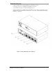
Equipment Overview 1. The power inlet/cord(s) connect the PT22 to the electrical power source. 2. Two RJ45 connectors for serial (RS-232) and Ethernet connection. 3. Two mini RJ11 connectors for temperature/humidity sensors. A number is printed above each PT22 outlet. These numbers can be used in commands that require an outlet name. For more information about outlet names, see the section “Outlet Naming and Grouping” in Chapter 3 – Operations. Figure 1.
IPv6 and Sentry Products Server Technology is introducing IPv6 “dual stack” support to the PT22 product line. IPv6 has been designed to succeed IPv4 as the dominant communications protocol for internet traffic, to avoid depletions of the IPv4 address space, and to allow more IP address growth. Many devices already in use support IPv6. IPv6 has several new operational methods: Static IPv6 Address: The IPv6 equivalent of Static IPv4.
Network-Enabled Modes NOTES: For all network-enabled modes described below, the unit will set an auto-configured IPv6 address, and if IPv6 router announcements are active, a stateless DHCP IPv6 address will also be set. Further, in all network-enabled modes, at least one IPv4 or one IPv6 address will be active. For maximum backward compatibility, the default network mode is “IPv4 only”. Network disabled: No IPv4 or IPv6 addresses available.
Viewing Network Status You can obtain the IPv6 network status through the firmware Web Interface (Network page) or Command Line Interface (CLI). For the CLI, use the show network command as follows: Switched CDU: show network Network Settings State: DHCP IPv6/IPv4 Network: Dual IPv6/IPv4 Link: Up Negotiation: Auto Speed: 100 Mbps Duplex: Full Dual IPv6/IPv4 AutoCfg IPv6: FE80::20A:9CFF:FE52:4104/64 IPv6 Address: FD01::1:B51A:E03C/64 IPv4 Address: 10.1.6.230 Subnet Mask: 255.255.0.0 IPv4 Gateway: 10.1.
Chapter 2: Installation Before installing your Sentry PT22, refer to the following lists to ensure that you have all the items shipped with the unit as well as all other items required for proper installation. Standard Accessories Mounting Hardware: Vertical models: Two removable flanges with four M4 screws. Two mounting L-brackets with nut plates, four sets of screws and washers. Optional button mounts. Horizontal models: Two removable L-brackets with M4 screws.
Safety Precautions This section contains important safety and regulatory information that should be reviewed before installing and using the Sentry PT22. For input and output current ratings, see the “Power Ratings” section in Appendix C: Technical Specifications. Only for installation and use in a Restricted Access Location in accordance with the following installation and use instructions.
Mounting 1. 2. 3. Select the appropriate bracket mounting points for proper mounting depth within the rack. Attach the brackets to these mounting points with two screws for each bracket. Install the enclosure into your rack, using the slots in each bracket. The slots allow about ¼ inch of horizontal adaptability to align with the mounting holes of your rack. NOTE: A mounting bracket kit for 23” wide racks or cabinets is available. For more information, contact your Server Technology sales reepresentative.
Connecting to the Unit Serial (RS232) port The PT22 is equipped with an RJ45 Serial RS-232 port for attachment to a PC or networked terminal server using the supplied RJ45 to RJ45 crossover cable and RJ45 to DB9F serial port adapter as required. For more information about the Serial RS-232 port, see the Data Connections section in Appendix C, Technical Specifications, in this manual. Ethernet port The PT22 is equipped with an RJ45 10/100Base-T Ethernet port for attachment to an existing network.
Chapter 3: Operations INTERFACES Outlet Naming and Grouping Usernames and Passwords 15 15 15 WEB INTERFACE Logging In System Summary Outlet Control Individual..............................................................................................................................20 Group....................................................................................................................................20 Power Monitoring Input Feeds ......................................................
TCP/IP Administration......................................................................................................... 68 HTTP Administration ........................................................................................................... 71 Telnet Administration........................................................................................................... 71 FTP Administration.....................................................................................................
Interfaces The PT22 unit has two interfaces: the Web interface accessed via the HTTP-enabled Ethernet connections, and the Command Line Interface (CLI) for serial and Telnet connections. Outlet Naming and Grouping For commands requiring an outlet name, you can specify the outlet command in one of two ways: a predefined absolute name or a descriptive name assigned by an administrator. For units with multiple infeed connectors, absolute names are specified by a period (.
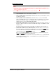
Web Interface The Web Interface provides web-based access to the firmware. The interface is designed with three major sections, illustrated below. 1. System Header: Shows device description, unit location, IP address and user/access information. 2. Navigation Bar: Provides access to unit configuration, control action, or status page. 3. Details Area: Current control/status information based on the page selected from the navigation bar. This example shows the Outlet Control > Individual page: Figure 3.
System Summary The System Summary is typically displayed as the default page at user login to the firmware Web Interface. If you do not have environmental monitor access for a PT22, your default page at login will be the Outlet Control page (shown in Figure 3.1 above). Both the System Summary page and the Outlet Control page display automatically at login and do not require enabling. The System Summary page contains general system, line, humidity, and temperature status information.
Active Users: Displays the number of active user sessions accessing the firmware. These sessions include serial, Telnet, SSH, and Web sessions. Active Users also shows sessions that an unauthorized user may be attempting to access. The number shown in Active Users changes instantly as the number of active user sessions change. NOTE: Depending on your web browser, multiple web accesses from the same machine are often treated as one user.
High Limit: Displays the high limit of the load, temperature, or humidity graph. These values depend on the sensor limits are cannot be set by the user. For example, a 100ºC high limit would be displayed for a temperature sensor graph in Celsius. as Status: One of several operating conditions: System Summary – Status Descriptions Icon Status Description Reading Unit is reading a new or restored sensor. Normal Indicates normal operation. Load High Infeed current load exceeds present High threshold.
Logical Group Separators Logical groups are separated by a thin blue line on the System Summary page as shown in the following example between Tower A_InfeedA and Tower B_InfeedA: This grouping includes master/link units in addition to some branched units. Up to three blue line dividers can be displayed on the System Summary page between all sensor groups. Outlet Control The Outlet Control section offers access to the Individual and Group outlet control pages.
Outlet State/Control State Field Values Outlet State Control State Description On On Outlet is on Off Off Outlet is off Off Pend On Outlet is off and about to turn on in response to a sequence timer Off Reboot Outlet is off and a Reboot action has been initiated On Idle On A restart has occurred: Last Control State has been maintained Off Idle Off A restart has occurred: Last Control State has been maintained On Wake On A power-loss has occurred: Wakeup State has been applied Off Wa
Shutdown The Shutdown section offers access to all Remote Shutdown configuration options. This section is available to administrative level users only. For additional information and configuration requirements, see the Remote Shutdown section in this manual. Outlets Enabling or disabling Remote Shutdown support: Select or deselect outlets to enable/disable Remote Shutdown support for in the Shutdown/Delay field and click Apply.
Configuring the LED display orientation: From the Display Orientation drop-down list, select Normal or Inverted, and click Apply. NOTES: Only specific PT22 models are equipped with an accelerometer chip that senses device orientation. If equipped, your unit automatically aligns the LED display orientation (depending on its current direction), and the option “Auto” displays in the Display Orientation drop-down list by default.
Setting the 3-phase load out-of-balance threshold: This setting to used for devices with 3-phase input voltages to notify of a system imbalance between the three phases of power. In the 3-Phase Load Out-of-Bounds Threshold field, enter a value from 0 to 100% and click Apply. Configuring the Command Line Interface (CLI) session timeout: Enter a timeout period (in minutes) in the CLI Session Timeout field, and click Apply. The valid timeout range is 1 to 1440 minutes (24 hours); the default is 5 minutes.
Creating a descriptive Environmental Monitor name: Click on the Environmental Monitor Names link. On the subsequent Environmental Monitor Names page, enter a descriptive name and click Apply. Creating descriptive sensor names: Click on the Sensor Names link. On the subsequent Sensor Names page, enter a descriptive name, and click Apply.
Enabling the DHCP boot delay: To enable the boot delay, check the Enable checkbox. To disable the boot delay, uncheck (clear) the checkbox. Click Apply. Enabling the Boot Delay option gives the PT22 approximately 90-seconds to establish a connection through a DHCP server. This interval allows various network component activities to occur as the PT22 powers up (such as obtaining SNTP time stamps for logging). This is the default state.
Telnet/SSH The Telnet/SSH configuration page enables or disables Telnet and SSH support and configures the port number that the Telnet or SSH server watches. Enabling or disabling Telnet or SSH support: Select Enabled or Disabled from the appropriate Server drop-down menu and click Apply. Changing the Telnet or SSH server port number: In the appropriate Port field, enter the port number and click Apply.
Setting the Sentry Power Manager (SPM) options: The Sentry Power Manager (SPM) is Server Technology’s enterprise management software product for the data center. The configuration options provided allow you to enable/disable SPM and reset the SPM password to its default. NOTE: The SPM options only apply if you are currently using Server Technology’s SPM software. In addition, the SPM options are only available on the HTTP/SSL web page. There are no equivalent SPM options on the Command Line Interface (CLI).
Towers The Towers configuration page is used for assignment and/or editing of: Descriptive names Serial and Model numbers Operation voltage types NOTE: If set at the factory, you cannot edit the serial number, model number, and voltage type. Creating a descriptive tower name: In the Tower Name field, enter a descriptive name and click Apply. Setting the tower serial number: In the Serial Number field, enter the serial number of the unit and click Apply.
Editing the UPS SNMP GET community string: In the SNMP GET Community String field, type the community string configured on the UPS device and click Apply. Enabling/Disabling UPS voltage polling: From the Poll UPS Voltage drop-down list, select Enabled or Disabled and click Apply. Editing the UPS SNMP port number: In the Port field, type the port number and click Apply. Associate the UPS with an infeed: Select the infeed(s) powered by the UPS and click Apply.
Users The Users configuration page is used for creation and removal of usernames, assignment of accessible outlets and group, assignment of privilege levels and the changing of user passwords. Creating a new user: Enter a user name in the Username field. Up to 16 alphanumeric and other typed characters (ASCII 33 to 126 decimal) are allowed; spaces are not allowed. Enter a password for the new user and verify in the Password and Verify Password fields. For security, password characters are not displayed.
Adding and Deleting serial port access: Click on the Ports link in the Access column for the associated user. On the subsequent User Ports page, select or deselect ports to be accessed by the user and click Apply. FTP The FTP configuration page is used for setup and maintenance of all settings required to perform an FTP firmware upload, configure automatic FTP updates or system configuration uploads/downloads. NOTE: The FTP page accepts both IPv4 and IPv6 formats in the Host field.
SNTP/Syslog The SNTP/Syslog configuration page is used for setup and maintenance of SNTP and Syslog support. For more information and the configuration requirements for Syslog support, see the Logging section in this manual. The SNTP/Syslog page sets the options for the SNTP server, time zone, Daylight Savings Time (DST) automatic clock adjustment, and Syslog server. About Daylight Savings Time(DST) Support for DST is disabled by default.
About SNMP versions: The firmware supports SNMP versions 1, 2, and 3. SNMP version 3 supports authentication and encryption on a per user basis. Authentication types are None and MD5. Encryption types are None and DES. If you use authentication, you must use encryption. Two SNMPv3 users are supported: one user with read-write (RW) access, and one user with read-only (RO) access Both users have the same configuration parameters, and you can configure each user independently.
Configuring general parameters for any SNMP version: Setting trap destinations: Type an IP address or hostname as necessary in the trap destination field(s) and click Apply. NOTE: Both IPv4 and IPv6 formats are accepted in the “Trap Destination 1” and “Trap Destination 2” fields. Setting the error trap repeat time: Type a time value in the Error Trap Repeat Time field and click Apply. The valid range is 1 to 65535 (in seconds).
Configuring Temperature Recovery Delta: Click on the Sensor Traps and Thresholds link. The Recovery Delta field allows configuration of the number of degrees of change needed to recover from a temperature alarm. After exceeding the high-temperature threshold, the temperature value must fall below the high-temperature threshold by the number of degrees specified in the Recovery Delta field before the sensor recovers.
Setting the user search filter: Enter the User Search Filter in the User Search Filter field and click Apply. Setting the group membership attribute: Enter the group membership attribute in the Group Membership Attribute Field and click Apply. Setting the group membership value type: Select the appropriate value from the drop-down menu and click Apply. Configuring the authentication order: Select Remote -> Local or Remote Only from the drop-down menu and click Apply.
TACACS+ The TACACS+ configuration page is used for setup and maintenance of all settings required to enable TACACS+ support. Enabling or disabling TACACS+ support: Select Enabled or Disabled from the TACACS+ drop-down menu and click Apply. Changing the TACACS+ server port: Enter the port number in the Port field and click Apply. Setting the TACACS+ server address: Enter the IP address or hostname in the Primary and/or Secondary Host field and click Apply.
RADIUS The Remote Authentication Dial-in User Service (RADIUS) configuration page is used for setup and maintenance of all settings required to enable RADIUS support. Enabling or disabling RADIUS support: Select Enabled or Disabled from the RADIUS drop-down menu and click Apply. Configuring the authentication order: Select Remote > Local or Remote Only from the drop-down menu and click Apply.
Email The Email configuration page is used for setup and maintenance Email log support. Enabling or disabling Email support: Select Enabled or Disabled from the Email Notifications drop-down menu and click Apply. Setting the SMTP server address: Enter the IP address or hostname in the SMTP Host field and click Apply. NOTE: Both IPv4 and IPv6 formats are accepted in the server address field. Changing the SMTP server port: Enter the port number in the SMTP Port field and click Apply.
View Log The View Log feature enables viewing of the internal system log. This features logs authentication attempts, power actions, configuration changes, and other system events. The system memory stores more than 4,000 entries in a continuously aging log. For permanent off-system log storage, the Syslog protocol is supported. NOTE: The system log is viewable only by users with administrative privileges.
Command Line Interface Logging In IMPORTANT: The Command Line Interface (CLI) was modified to allow both IPv4 and IPv6 settings. Logging in through Telnet requires directing the Telnet client to the configured IP address of the unit.
Administrative Command Summary Add Porttouser Grants a user access to one or all serial/Pass-Thru ports Create User Adds a user account Delete Portfromuser Removes access to one or all serial/Pass-Thru ports List User Displays all accessible ports for a user List Users Displays privilege levels for all users Remove User Deletes a user account Restart Performs a warm boot Set Banner Set the pre-login banner text Set DHCP Enables or disables DHCP support Set DHCP Boot Delay Enables or disab
Administrative Command Summary (continued…) Set Option Strong Passwords Enables or disables strong password requirements Set Option Tempscale Sets the Environmental Monitor temperature scale Set Option Web Timeout Sets the web session (Web Interface) timeout period Set Port Name Specifies a descriptive field for a serial/Pass-Thru port Set Port DSR Check Sets the DSR active signal checking for a serial/Pass-Thru port Set Port Speed Set the connection speed for all serial/Pass-Thru ports Set Port
To display the names of commands that you can execute: At the command prompt, press Enter. A list of valid commands for the current user appears. Operations Commands Operations commands manage outlet states, provide information about the PT22 environment and control session operations. Turning outlets on: The On command turns on one or more outlets. When the command completes, a display indicating all outlets affected and their current states will be displayed.
Rebooting outlets: The Reboot command reboots one or more outlets. This operation turns the outlet(s) off, delays for a user configurable period and then turns the outlet(s) on. When the command completes, a display indicating all outlets affected and their current states will be displayed. NOTE: You will need to re-issue the Status command to verify that the outlets have rebooted.
Displaying accessible outlets: The List Outlets command displays accessible outlets for the current user. The display includes the absolute and descriptive name of all outlets assigned to the current user. To display accessible outlets: At the Switched CDU: prompt, type list outlets and press Enter. Example The follow command displays all accessible outlets for the current user: Switched CDU: list outlets Outlet ID Outlet Name .A1 .
Displaying infeed status: The Istat command displays the status of one or more infeeds. This display includes the infeed absolute and descriptive names and the input status and current load reported to the PT22 by the infeed, branch, or phase. To display status of one or more infeeds: Type istat and press Enter. Examples The following command displays the infeed status: Switched CDU: istat Input Feed ID Input Feed Name Input Status Voltage Load Power .AA TowerA_InfeedA On 121.0 0.
Starting a new session: The Login command activates the Username: prompt. The current session ends, allowing a user to log in and start a new session under a different username. To start a new session: At the Switched CDU: prompt, type login and press Enter. The Username: prompt appears. Ending a session: The Quit or Logout commands ends a session. A session ends automatically when no activity is detected for five minutes, or upon loss of connection.
Removing a user account: The Remove User command removes a user account. NOTE: You can remove the predefined user account admn only if another user account has been granted administrative privileges using the Set User Admnpriv command. For security, Server Technology recommends first creating a new administrative user account with administrative rights before removing the default account admn. To remove a user account: At the Switched CDU: prompt, type remove user, optionally followed by a username.
Displaying the access privilege levels: The List Users command displays all defined users with their access privilege level. To display user access privilege levels: At the Switched CDU: prompt, type list users and press Enter.
Deleting group access for a user: The Delete GroupFromUser command removes a user’s access to a group. You cannot remove access to any group for an administrative level user. To delete group access for a user: At the Switched CDU: prompt, type delete GroupFromUser, optionally followed by a group name and a username. Press Enter. Adding serial port access to a user: The Add PortToUser command grants a user access to the serial port.
Input Feed Administration Creating a descriptive infeed name: The Set Infeed Name command assigns a descriptive name to an infeed. This descriptive name is displayed when the Show Traps command is issued. To create a infeed name: At the Switched CDU: prompt, type set infeed name followed by the absolute infeed name, then a descriptive name of up to 24 alphanumeric and other typed characters - (ASCII 33 to 126 decimal) are allowed; spaces are not allowed. Press Enter.
Outlet Administration Setting the sequencing interval: The Set Outlet SeqInterval commands sets the power on sequencing interval for all outlets. To set the sequencing interval: At the Switched CDU: prompt, type set outlet seqinterval all, followed by a value from 0 to 15 (in seconds) and press Enter. Setting the reboot delay: The Set Outlet RebootDelay commands sets the reboot delay for all outlets.
Displaying outlet information: The Show Outlets command displays information about all outlets. This information includes: Sequencing and reboot timer values Descriptive outlet name, if applicable Outlet wakeup state and Post-On settings To display outlet information: At the Switched CDU: prompt, type show outlets and press Enter. Example The following command displays all outlet information: Switched CDU: show outlets Outlet ID Outlet Name Wakeup State Post-On Delay (seconds) .A1 .A2 .
Setting the infeed maximum load capacity The Set Infeed LoadMax command is use to edit the input maximum load capacity. To set the infeed maximum load capacity: At the Switched CDU: prompt, type set infeed loadmax, followed by the absolute infeed name, and a value from 1 to 255 (in amperes). Press Enter. Example The following commands sets the maximum load capacity for input .AA to 15 amperes: Switched CDU: set infeed loadmax .
Setting the tower model number: The Set Tower Model command is use to set the product model number. NOTE: If set at the factory, you cannot edit the model number. To set the tower model number: At the Switched CDU: prompt, type set tower model, followed by the absolute tower name, and the tower model number. Press Enter. Example The following command sets the model number for tower .A to ‘CW-8H1-C20’: Switched CDU: set tower prodsn .
Group Administration Creating a group name: The Create Group command creates a new group name. To create a group name: At the Switched CDU: prompt, type create group optionally followed by a descriptive name of up to 24 alphanumeric and other typed characters; (ASCII 33 to 126 decimal) are allowed; spaces are not allowed. Group names are not case sensitive. Press Enter.
Environmental Monitor Administration Creating a descriptive Environmental Monitor name: The Set Envmon Name command assigns a descriptive name to the integrated Environmental Monitor. This descriptive name is displayed when the Evnmon command is issued.
Enabling or disabling active signal checking for serial connections: The Set Port DSRCheck command enables or disables active signal checking for serial connections to devices attached to any of the available serial ports. To enable or disable active signal checking for serial connections: At the Switched CDU: prompt, type set port dsrcheck console, on or off, and press Enter. Setting the serial port timeout value: The Set Port Timeout command is used to set the serial port inactivity timeout period.
Creating a location description: The Set Location command specifies text that appears in the Web control screen’s Location field. The text is also appended to a Welcome to banner that appears when a user successfully logs in serially or through a Telnet session. If you do not issue this command, or if you issue this command without specifying any text, the control screen’s Location field will be blank and no Welcome to banner will be displayed.
Setting the system 3-phase load out-of-balance threshold: The Set System Balance command is used to set the percentage out-of-balance threshold for loads on 3phase input voltage devices. To set the system 3-phase load out-of-balance threshold: At the Switched CDU: prompt, type set system balance, followed a value from 0 to 100 (in percentage) and press Enter.
Setting the LED display orientation: The Set Option Display command is used to configure the Current LED(s) display orientation. To set the LED display orientation: At the Switched CDU: prompt, type set option display, followed by normal or inverted and press Enter. Example The following set the LED display orientation to Inverted: Switched CDU: set option display inverted NOTES: Only specific PT22 units are equipped with an accelerometer chip that senses device orientation.
Setting the outlet sequence order: The CDU lets you configure the power-on sequence of outlets. The Normal option powers-on outlets in ascending numeric order by outlet number, for example, from outlet 1-8. The Reversed option powers on outlets in descending order by outlet number; for example, from outlet 8-1. The Reversed option is useful when the CDU is mounted with inverted orientation and the last outlet (in this example, outlet 8) is in the first position.
To enable or disable coldboot alert: Upon a coldboot of the system (if the Coldboot Alert feature is enabled), the system sends a ½ second RS-232 break out on any serial ports that are also enabled. The Set Option Coldboot Alert command enables or disables the Coldboot Alert feature. To enable or disable coldboot alert: At the Switched CDU: prompt, type set option cbalert, followed by enabled or disabled, and press Enter.
Enabling or disabling the Cisco EnergyWise network: NOTE: Only commands through the CLI are supported for the Cisco EnergyWise network. There is no firmware webbased interface for EnergyWise. Enabling EnergyWise requires a system restart. The Set EnergyWise command enables or disables the EnergyWise network support: To enable or disable EnergyWise: At the Switched CDU: prompt, type set energywise, followed by enabled or disabled, and press Enter.
To set a blank EnergyWise secret: A blank secret is acceptable. At the Switched CDU: prompt, type set energywise secret, do not type in the Secret field, and press Enter twice (to bypass the Secret field and then VerifySecret field.
TCP/IP Administration NOTE: You will need to restart the PT22 after setting or changing any TCP/IP configurations. Enabling or disabling DHCP support: The Set DHCP command enables or disables DHCP support. To enable or disable DHCP support: At the Switched CDU: prompt, type set dhcp, followed by enabled or disabled, and press Enter. Enabling or disabling DCHP boot delay: The Set DHCP Boot Delay command enables or disables the DHCP boot delay option.
Setting the IP address: The Set Ipaddress command sets the TCP/IP address of the network interface controller. To set the IP address: At the Switched CDU: prompt, type set ipaddress, followed by the IP address and press Enter. Example The following command sets the IP address to 12.34.56.78: Switched CDU: set ipaddress 12.34.56.78 Setting the subnet mask: The Set Subnet command sets the subnet mask for the network the PT40 will be attached to.
To display network configuration information: At the Switched CDU: prompt, type show network and press Enter. Example The following command displays the network configuration information: Switched CDU: show network Network Settings State: DHCP IPv6/IPv4 Network: Dual IPv6/IPv4 Link: Up Negotiation: Auto Speed: 100 Mbps Duplex: Full Dual IPv6/IPv4 AutoCfg IPv6: FE80::20A:9CFF:FE52:4104/64 IPv6 Address: FD01::1:B51A:E03C/64 IPv4 Address: 10.1.6.230 Subnet Mask: 255.255.0.0 IPv4 Gateway: 10.1.1.
HTTP Administration NOTE: You will need to restart the PT22 after setting or changing any Telnet/Web configurations. Enabling and disabling HTTP support: The Set HTTP command is used to enable or disable HTTP support. To enable or disable HTTP support: At the Switched CDU: prompt, type set http, followed by enabled or disabled and press Enter. Changing the HTTP server port: With HTTP support enabled, the HTTP server watches and responds to requests on the default HTTP port number 80.
FTP Administration You can upload new versions of firmware into the PT22 using File Transfer Protocol (FTP). This allows access to new firmware releases for firmware improvements and new features additions. The following commands are used to configure the unit for an FTP firmware upload. Setting the FTP host address: The Set FTP Host command sets the FTP host IP address or hostname allowing for firmware file uploads.
Setting the directory for the file to be uploaded: The Set FTP Directory command sets the directory for the firmware file to be uploaded. To set the FTP directory: At the Switched CDU: prompt, type set ftp directory, followed by the directory and press Enter.
Displaying FTP configuration information: The Show FTP command displays all FTP configuration information. FTP Host IP address FTP Host username and password Firmware filepath and filename To display FTP configuration information: At the Switched CDU: prompt, type show ftp and press Enter. Example The following command displays the FTP configuration information: Switched CDU: show ftp FTP Configuration Host: Username: Password: Directory: Filename: 10.1.2.100 taxe ******* /firmware/7.
Setting the SNTP server address: The Set SNTP command is used to set the primary and secondary SNTP server addresses. To set the SNTP server address: At the Switched CDU: prompt, type set sntp, followed by primary or secondary, and the SNTP server IP address or hostname. Press Enter. NOTES: The primary/secondary IP addresses contact the SNTP server; these addresses are populated with the external NTP pool time zones “2.pool.ntp.org” and “1.pool.ntp.
Displaying SNTP configuration information: The Show SNTP command displays all SNTP configuration information. To display SNTP configuration information At the Switched CDU: prompt, type show sntp and press Enter. Example The following command displays the SNTP configuration information: Switched CDU: show sntp Date/Time: 2013-04-13 Primary Host: Secondary Host: Local GMT Offset: Use DST: Start Date: Start Time: End Date: End Time: 204.152.184.72 1.pool.ntp.
Removing a UPS record: The Remove UPS command removes a UPS record. To remove a UPS record: At the Switched CDU: prompt, type remove ups and press Enter. At the prompt, type the index number of the UPS to be removed and press Enter.
Changing the UPS SNMP port: With a UPS record configured, the PT22 sends data requests to the default UPS SNMP port number 161. This port number can be changed using the Set UPS Port command. To change the UPS SNMP port: At the Switched CDU: prompt, type set ups port and press Enter. At the prompt, type the index number for the UPS record to be changed and press Enter. At the prompt, type the desired port number and press Enter.
Adding an infeed to a UPS: The Set UPS AddInfeed command adds a logical association of an infeed to a UPS. To add an infeed to a UPS: At the Switched CDU: prompt, type set ups addinfeed and press Enter. At the prompt, enter the index number for the UPS record to be changed and press Enter. At the prompt, type the absolute infeed ID of the desired infeed, and press Enter. Example The following command associates infeed .
Feature Administration Displaying activated special features: The Show Features command displays all activated special features for the device. To display activated special features: At the Switched CDU: prompt, type show features and press Enter. Example The following command displays all activated special features: Switched CDU: show features Activated Features: Smart Load Shedding NOTE: A restart of the PT22 is required after activating new special features.
Chapter 4: Advanced Operations SSL Enabling and Setting up SSL Support SSL Technical Specifications 82 82 82 SSH Enabling and Setting up SSH Support SSH Technical Specifications 83 83 84 SNMP/THRESHOLDS MIB, OID and Support Enabling and Setting up SNMP Support SNMP Traps Configuring Traps 85 85 87 90 93 LDAP Enabling and Setting up LDAP Support Configuring LDAP Groups LDAP Technical Specifications TACACS+ Enabling and Setting up TACACS+ Support Configuring TACACS+ Privilege Levels TACACS+ Technical S
SSL Secure Socket Layers (SSL) version 3 enables secure Web sessions between a Remote Power Manager and a remote user. SSL provides two chief features designed to make TCP/IP (Internet) transmitted data more secure: Authentication – The connecting client is assured of the identity of the server. Encryption – All data transmitted between the client and the server is encrypted rendering any intercepted data unintelligible to any third party.
SSH Secure Shell (SSH) version 2 enables secure network terminal sessions between a Remote Power Manager and a remote user over insecure network. SSH provides an encrypted terminal sessions with strong authentication of both the server and client, using public-key cryptography and is typically used as a replacement for unencrypted Telnet.
SSH Technical Specifications Secure Shell (SSH) version 2 Asymmetric Cryptography: Diffie-Hellman DSA/DSS 512-1024 (random) bits per NIST specification Symmetric Cryptography: AES256-CBC RIJNDAEL256-CBC AES192-CBC RIJNDAEL192-CBC AES128-CBC RIJNDAEL128-CBC Message Integrity: HMAC-SHA1-160 HMAC-MD5-128 3DES-192-CBC BLOWFISH-128-CBC ARCFOUR-128 HMAC-SHA1-96 HMAC-MD5-96 Authentication: Username/Password Session Channel Break Extension (for RS232 Break) 84 Advanced Operations Installation and Operations M
SNMP/Thresholds The PT22 supports the Simple Network Management Protocol (SNMP). This allows network management systems to use SNMP requests to retrieve information and control power for the individual outlets. The unit includes an SNMP v2c agent supporting standard MIB I and MIB II objects. A private enterprise MIB extension (Sentry3 MIB) is also supported to provide remote power control. For more information about enabling and configuring SNMP, see the SNMP section in this manual.
Setting the Get/Set community strings: NOTE: The default for SNMP support is Enabled. When Server Technology products are shipped, the default SNMP configuration for the GET community string is set to “public” and the SET community string is left blank. The PT22 supports two SNMP community strings (SET and GET) that provide varying levels of access to objects defined in the Sentry3 MIB. Valid community strings are 1 to 24 characters.
SNMP v3 Command Summary Command Description Set SNMP IP Restrict Allows SNMP Get and Set requests from defined trap destinations only Set SNMP V3 Enables or disables SNMP v3 support Set SNMP V3 RO Username Sets the SNMP V3 read-only username.
Setting the SNMP v3 read-only (RO) authentication password: The Set SNMP RO Auth Password command sets the SNMP v3 RO authentication password. A valid authentication password can be set to any value between 1-40 characters. A blank password will clear the string. To set the RO authentication password: At the Switched CDU: prompt, type set snmp v3 roauthpass, and press Enter. Setting the SNMP v3 read-only (RO) privacy type : The Set SNMP RO Priv Type command sets the SNMP v3 RO privacy type.
Setting the SNMP v3 trap username: The Set SNMP Trap Username command sets an optional username for display on SNMP activity logs to identify user actions. At the Switched CDU: prompt, type set snmp v3 trapusername, and press Enter. The trap username can be 1-31 alphanumeric characters; spaces are allowed; and the name is case sensitive. Setting the error trap repeat timer: The Set SNMP Traptime command sets the timer period between repeated error condition traps.
To display SNMP configuration information: At the Switched CDU: prompt, type show snmp and press Enter.
Status trap A Status trap is generated when an error condition occurs on a tower, infeed, Environmental Monitor or individual sensor. Status traps include the reported status, the location of the PT22, and identifier/name of the affected tower, infeed, outlet, environmental monitor, or sensor. Any error state generates a Status trap and triggers the trap timer. A new trap is generated at the end of every timer period until the Status returns to a non-error status. All status traps are enabled by default.
Load Trap The Load trap is generated whenever the total input load on an infeed exceeds a preset threshold. Load traps include the reported input load, load status, Location of the PT22, and identifier/name of the affected infeed. Any error state generates a Load trap and triggers the trap timer. A new trap is generated at the end of every timer period until the Load returns to a non-error status.
Configuring Traps SNMP Trap Command Summary Command Description Set Trap Tower Status Enables or disables the Tower Status trap Set Trap Infeed Status Enables or disables the Infeed Status trap off Set Trap Infeed Load Enables or disables the Infeed Load trap Set Trap Infeed HighThresh Sets the Infeed Load trap high limit Set Trap Outlet Change Enables or disables the Outlet Change trap Set Trap Outlet Status Enables or disables the Outlet Status trap Set Trap EM Status Enables or disables th
Setting the Infeed Load limit: The Set Trap Infeed Loadhigh command is used to set the upper load limits for an input feed. To set the infeed load limit: At the Switched CDU: prompt, type set trap infeed loadhigh, followed by the infeed name, and a value from 0 to 255 in amperes. Press Enter. Example The following command sets the infeed load limit for the second infeed on the first tower to 25 amperes, using the absolute name of the infeed: Switched CDU: set trap infeed loadhigh .
Configuring Temperature Recovery Delta: The Temperature Recovery Delta command allows configuration of the number of degrees of change needed to recover from a temperature alarm. To configure the temperature recovery delta: At the Switched CDU: prompt, type set event temp tempdelta, followed by the sensor name, the number of degrees for the recovery delta, and press Enter. NOTE: The acceptable value range for the Recovery Delta field is 0-10 degrees for Celsius and 0-18 degrees for Fahrenheit.
Displaying trap configuration information: The Show Traps command displays information about all traps. To display trap information: At the Switched CDU: prompt, type show traps and press Enter. Example The following command requests trap configuration information: Switched CDU: show traps Tower trap configuration: Tower ID Tower Name Status Trap .A .B Florida_HQ_1 Florida_HQ_2 ON ON More (Y/es N/o): y Input feed trap configuration: Input Feed ID Input Feed Name Status Trap Load Trap .
LDAP The PT22 supports Lightweight Directory Access Protocol (LDAP) Version 3. This support enables authentication with LDAP servers; user accounts do not need to be individually created locally on each unit. This allows administrators to pre-define and configure (in each PT22 and in the LDAP server) a set of necessary LDAP Groups, and access rights for each. User’s access rights can then be assigned or revoked simply by making the user a member of one-or-more pre-defined PT22 LDAP Groups.
Enabling and Setting up LDAP Support There are a few configuration requirements for properly enabling and setting up LDAP support. Below is an overview of the minimum requirements. Directory Services server configuration requirements: 1. 2. Define at least one LDAP group. Assign users to that LDAP group. PT22 configuration requirements: 1. 2. 3. 4. 5. 6. Enable LDAP support. Define the IP address and domain component of at least one Directory Services server.
Setting the LDAP bind password type: The Set LDAP Bind command sets the password type used in the bind requests. The PT22 supports two standard LDAP bind methods: Simple and MD5. The Simple method uses unencrypted delivery of a username-password over the network to the Active Directory server for authentication. The MD5 digest method provides much stronger protection using 1-way hash encoding that never transmits the username-password over the network. NOTE: Windows 2000 supports only Simple binding.
Setting the group membership value type: The Set LDAP GroupType command is used to specify whether the values of Group Membership Attribute represent the Distinguished Name (DN) of a group or just the name of the group. To set group membership value type: At the Switched CDU: prompt, type set ldap grouptype followed by DN or Name and press Enter.
Setting the authentication order: The Set Authorder command sets the authentication order for remote authentication sessions. The PT22 supports two methods for authentication order - Remote -> Local and Remote Only. The Remote -> Local method first attempts authentication with the Active Directory server and if unsuccessful with the local user database on the unit. The Remote Only method attempts authentication only with the Active Directory server and if unsuccessful, access is denied.
Setting the DNS IP address: The Set DNS command sets the TCP/IP address of the Domain Name server (DNS). NOTE: LDAP requires the definition of at least one Domain Name System (DNS) server. To display the DNS configuration information, use the Show Network command as described on page 69. To set the DNS IP address: At the Switched CDU: prompt, type set, followed by dns1 or dns2 and the Domain Name server’s IP address. Press Enter. NOTE: Both IPv4 and IPv6 formats are accepted for IP address.
Setting LDAP group access level privileges: The Set LDAPGroup Access command sets the access level privileges for an LDAP group. The PT22 has four defined access privilege levels; Admin, User, On-Only, and View-Only. To set the access level privilege for an LDAP group : At the Switched CDU: prompt, type set ldapgroup access, followed by admin, user, ononly or viewonly, optionally followed by a LDAP group name and press Enter.
Deleting outlet access for an LDAP group: The Delete OutletFromLDAP command removes an LDAP group’s access to one or all outlets. You cannot remove access to any outlet for an administrative level group. To delete outlet access for an LDAP group: At the Switched CDU: prompt, type delete outletfromldap, optionally followed by an outlet name and a group name. Press Enter, or Type delete outletfromldap all, followed by a group name and press Enter.
Displaying LDAP Group access: The List LDAPGroup command displays all access rights for an LDAP group. To display LDAP Group access: At the Switched CDU: prompt, type list ldapgroup, optionally followed by a group name. Press Enter. Example The following command displays information about the LDAP group PowerUser: Switched CDU: list ldapgroup poweruser Username: PowerUser Outlet ID Outlet Name .A1 .
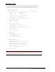
LDAP Technical Specifications LDAP Authentication Process Simple Bind Authentication Process Client LDAP Server MD5 Bind Authentication Process Sentry Client Initiate Sentry session Prompt for login credentials Initiate Sentry session Prompt for login credentials Authentication request with Usename/ Password Simple bind using Search Bind DN & Password Authentication request with Usename/ Password SASL Digest-MD5 bind using uppercase username & entered password LDAP Server Sentry Successful Bin
TACACS+ The PT22 supports the Terminal Access Controller Access Control System (TACACS+) protocol. This enables authentication and authorization with a central TACACS+ server; user accounts do not need to be individually created locally on each unit. This allows administrators to pre-define and configure (in each unit, and in the TACACS+ server) a set of necessary TACACS+ privilege levels, and users access rights for each.
Setting the TACACS+ server address: The Set TACACS Host command sets the IP address or hostname of the TACACS+ server. NOTE: Both IPv4 and IPv6 formats are accepted for IP address or hostname. To set the TACACS+ server address: At the Switched CDU: prompt, type set tacacs, followed by host1 or host2 and the TACACS+ server’s IP address or hostname. Press Enter. Examples The following command sets the primary TACACS+ server address to 98.76.54.32: Switched CDU: set tacacs host1 98.76.54.
Setting the authentication order: The Set Authorder command sets the authentication order for remote authentication sessions. The PT22 supports two methods for authentication order - Remote -> Local and Remote Only. The Remote -> Local method first attempts authentication with the TACACS+ server and if unsuccessful with the local user database on the PT22 device. The Remote Only method attempts authentication only with the TACACS+ server and if unsuccessful, access is denied.
Granting and removing input status viewing privileges: The Set TacPriv Envmon command grants or removes input status viewing privileges to/from a TACACS+ account. To grant or remove input status viewing privileges for a TACACS+ account: At the Switched CDU: prompt, type set tacpriv envmon, followed by on or off, optionally followed by a TACACS+ account number and press Enter.
Adding outlet group access to a TACACS+ account: The Add GroupToTACACS command grants a TACACS+ account access to an outlet group. To grant access for more than one outlet group, you must use multiple Add GroupToTACACS commands. To grant outlet group access to a TACACS+ account: At the Switched CDU: prompt, type add grouptotacacs, optionally followed by an outlet group name and a TACACS+ account number. Press Enter.
Members of the TACACS privilege level 1 account can access the following outlets, outlet groups and serial ports: outlet A1 which has a descriptive name of DataServer_1, outlet A2 which has a descriptive name of WebServer_1, group ServerGroup_1 group ServerGroup_2 and Console serial port.
RADIUS The PT22 supports the Remote Authentication Dial-in User Service (RADIUS) protocol. RADIUS provides a centralized network protocol to enable remote authentication and authorization, such as user names and passwords. With a central RADIUS server, user accounts do not need to be individually created locally on each unit. This allows administrators to pre-define and configure (in each PT22 and in the RADIUS server), a set of necessary RADIUS privilege levels and user access rights for each level.
Setting the RADIUS server address: The Set RADIUS Server command sets the IP address or hostname of the primary or secondary server used for RADIUS authentication requests. NOTE: Both IPv4 and IPv6 formats are accepted for primary/secondary IP address or hostname. To set the RADIUS server address: At the Switched CDU: prompt, type set radius, followed by primary or secondary, followed by server, and the RADIUS server’s IP address or hostname (maximum 63 characters). Press Enter.
Setting the number of RADIUS server retries: The Set RADIUS Retries command specifies the number of times an authentication request is sent to the RADIUS server. The PT22 will attempt authentication with the primary server until the number of retries is reached, then will attempt authentication with the secondary server. If the PT22 does not receive a response from these attempts, the authentication request will be rejected.
Vendor-Specific Attributes (VSA): Server Technology has defined and formatted RADIUS vendor-specific attributes (VSA) in the dictionary.sti file, which is available from Server Technology. The PT22 unit is configured to recognize and use the configuration values in the file as specified by the network administrator, indicating to the RADIUS server that the defined attributes are based on Server Technology’s unique enterprise vendor code. Using the format of the dictionary.
Logging The PT22 supports logging of system events both internally and externally. An internal log of more than 4000 events is automatically maintained and is reviewable by administrative users. For permanent/long-term log storage, the unit supports the Syslog protocol. And for immediate notification, the unit supports Email notifications. Log entries include a sequential entry number, a date/time stamp and an event message.
Displaying Syslog configuration information: The Show Syslog command displays Syslog configuration information. To display the Syslog configuration information: At the Switched CDU: prompt, type show syslog and press Enter. Example The following command displays the Syslog configuration information: Switched CDU: show syslog SYSLOG Configuration Primary Host: Secondary Host: Port: 10.1.2.
Changing the SMTP server port: With SMTP support enabled, the PT22 sends SMTP requests to the default SMTP port number 25. This port number can be changed using the Set Email SMTP Port command. To change the TACACS port: At the Switched CDU: prompt, type set email smtp port, followed by the port number and press Enter.
Setting the ‘To’ email address: The Set Email PrimaryTo and Set Email SecondaryTo commands set the recipient email addresses. To set the ‘To’ email address: At the Switched CDU: prompt, type set email, followed by primaryto or secondaryto and the destination email address. Press Enter. Examples The following command sets the primary ‘to’ email address to DayAdmin@servertech.com: Switched CDU: set email primaryto DayAdmin@servertech.
Upload/Download The unit supports the ability to upload and download system configurations using a standard FTP client. This feature enables for backup and restoration of system configuration as well as upload of ‘template’ configurations to ease large initial equipment deployments.
Upload/Download Process GET a configuration file (Download): 1. Open the FTP client. In a Windows environment, in the Run window type ftp and press Enter. 2. At the prompt, type open, followed by the IP address of the PT22 and press Enter. FTP> open 12.34.56.78 3. Authenticate with the appropriate administrative username and password. 4. At the prompt, type get, followed by the filename and press Enter. FTP> get config.bin 5.
Remote Shutdown The PT22 supports the ability to initiate an orderly shutdown of remote servers, protecting open application files prior to the server being powered down. Shutdown signaling is initiated over the existing TCP/IP network and requires the use of a Remote Shutdown Agent.
Supported Operating Systems Remote Shutdown Agents are available for the following operating systems: Windows Linux Unix Novell Netware 2000, 2003, XP Red Hat 7.3, 8.0 Red Hat Enterprise 2.1 ES (update 5), 3.0 ES (update 4) Novell SUSE Linux Enterprise Server HP-UX 11.0, 11i v1, 11i v2 IBM AIX 4.3, 5.3 Sun Solaris 8, 9, 10 6 The Remote Shutdown Agents are available for download from the Server Technology website at www.servertech.com Shutdown Agent Installation Windows 1. 2. 3. 4.
Enabling and Setting up Remote Shutdown Support Remote Shutdown Command Summary Command Description Set Outlet Host Sets the target server Host IP address or hostname Set Outlet Shutdown Enables or Disables Remote Shutdown Set Outlet Shutdown Delay Sets the outlet Remote Shutdown delay Set Outlet Script Enables or disables shutdown script delays Set Outlet Script Delay Sets the outlet shutdown script delay Show Shutdown Displays Remote Shutdown configuration information Enabling or disabling R
Setting the shutdown script delay: The Set Outlet Script Delay command sets the shutdown script delay for an outlet. To set the shutdown script delay: At the Switched CDU: prompt, type set outlet script delay, followed by the outlet ID, and a value from 1 to 15 (in minutes). Press Enter. Example The following command sets the shutdown script delay for outlet .a1 to 10 minutes: Switched CDU: set outlet shutdown delay .
Chapter 5: Appendices Appendix A: Resetting to Factory Defaults You can reset the non-volatile RAM that stores all configurable options. This clears all administratoreditable fields and resets all command line configurable options to their default values, including all user accounts. You can reset the unit to factory defaults from the command line or the Web interface, or by pressing the reset button. You must have administrator-level privileges to issue the command.
Appendix C: Technical Specifications Domestic Models Model Voltage Inlets * PT22-H004-1-02 PT22-H004-2-02 100-120V, 50/60Hz 208-240V, 60Hz 4 x IEC 60320 C20 4 x IEC 60320 C20 Outlets 4 x IEC 60320 C19 4 x IEC 60320 C19 International Models Model Voltage Inlets* PT22-H004-2-02 230V, 50/60Hz 4 x IEC 60320 C20 Outlets 4 x IEC 60320 C19 * Input cord sets selected at time of purchase. For more information, contact your Server Technology sales representative.
Data Connections RS-232 port PT22 are equipped standard with an RJ45 DTE RS-232c serial port. This connector can be used for direct local access or from other serial devices such as a terminal server. An RJ45 crossover cable is provided for connection to an RJ45 DCE serial port.
Regulatory Compliance Product Safety Units have been safety tested and certified to the following standards: USA/Canada European Union UL 60950-1:2007 and CAN/CSA 22.2 No. 60950-1-07 EN60950-1:2006+A11+A1+A12 This product is also designed for Norwegian IT power system with phase-to phase voltage 230V. USA Notification NOTE: This equipment has been tested and found to comply with the limits for a Class A digital device, pursuant to part 15 of the FCC Rules.
Recycling Server Technology Inc. encourages the recycling of its products. Disposal facilities, environmental conditions and regulations vary across local, state and country jurisdictions, so Server Technology encourages consultation with qualified professional and applicable regulations and authorities within your region to ensure proper disposal. Waste Electrical and Electronic Equipment (WEEE) In the European Union, this label indicates that this product should not be disposed of with household waste.
Server Technology HEADQUARTERS – NORTH AMERICA EMEA APAC Server Technology, Inc. 1040 Sandhill Drive Reno, NV 89521 United States +1.775.284.2000 Tel +1.775.284.2065 Fax sales@servertech.com www.servertech.com www.servertechblog.com Server Technology Intl Sienna Court The Broadway Maidenhead Berkshire SL6 1NJ United Kingdom +44 (0) 1628 509053 Tel +44 (0) 1628 509100 Fax salesint@servertech.com Server Technology, Inc. Singapore +65 (0) 6829 7008 Tel +65 (0) 6234 4574 Fax salesint@servertech.