Smart Cabinet Distribution Unit Installation and Operations Manual • CS/CL-3AVx • CS/CL-12Vx • CS/CL-16Vx • CS/CL-21Vx • CS/CL-24Vx • CS/CL-36Vx • CS/CL-12HDx • CS/CL-48VDx • CS/CL-54VDx • CS/CL-84VDx © 2005-2008 Server Technology, Inc. All rights reserved.
Instructions This symbol is intended to alert the user to the presence of important operating and maintenance (servicing) instructions in the literature accompanying the appliance. Dangerous Voltage This symbol is intended to alert the user to the presence of un-insulated dangerous voltage within the product’s enclosure that may be of sufficient magnitude to constitute a risk of electric shock to persons.
Table of Contents CHAPTER 1: INTRODUCTION 4 Quick Start Guide.............................................................................................................................4 Technical Support ............................................................................................................................4 Equipment Overview........................................................................................................................
Chapter 1: Introduction Quick Start Guide The following instructions will help you quickly install and configure your Smart CDU for use in your data center equipment cabinet. For detailed information on each step, go to the page number listed to the right. 1. 2. 3. 4. 5. 6. 7. Mount the Smart CDU ...............................................................................................................7 Connect to the power source .......................................................................
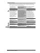
Equipment Overview 1. 2. 3. 4. The power inlet/cord(s) connects the CDU to the electrical power source. The Input Current LED(s) displays the current load for each infeed or electrical phase per infeed. Two RJ45 connectors for Serial (RS-232) and Ethernet connection Two mini RJ11 connectors for Temperature/Humidity sensors. 4 3 4 3 2 2 3 4 1 2 2 1 1 1 Figure 1.
Chapter 2: Installation Before installing your Sentry Smart Cabinet Distribution Unit (CDU), refer to the following lists to ensure that you have all the items shipped with the unit as well as all other items required for proper installation. Standard Accessories • • • Mounting hardware: Vertical models Two removable flanges with four M4 screws. Two mounting L-brackets with nut plates, four sets of screws and washers. Optional button mounts. Horizontal models Two removable flanges with M4 screws.
Safety Precautions This section contains important safety and regulatory information that should be reviewed before installing and using the Sentry Smart Cabinet Distribution Unit. For input and output current ratings, see Power Ratings in Appendix C: Technical Specifications. Only for installation and use in a Service Access Location in accordance with the following installation and use instructions. This equipment is designed to be installed on a dedicated circuit.
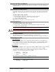
Installing the Power Input Retention Bracket For units with a total maximum output <30A, it may be necessary to install the power input retention bracket prior to mounting the unit within the rack. To install the power input retention bracket: 1. 2. Remove the two screws attaching the IEC 60320 C19 inlet to the enclosure. Assemble and attach the retention bracket to the enclosure as shown. Figure 2.1 Retention Bracket assembly Mounting Figure 2.2 Mounting Horizontal/Rack 1. 2. 3.
Attaching the Expansion Module If supported, connect the Linking Smart CDU with the provided RJ12 crossover cable at the Link port on the Smart CDU. NOTE: The overall length of the RJ12 crossover cable should not exceed 10 feet. Connecting to the Power Source On 30A units, the input power cord is attached to the base of the unit. On units with a total maximum output <30A, you must first attach the power cord to the unit before connecting the unit to the power source. To attach a power cord to the unit: 1.
Chapter 3: Operations INTERFACES Usernames and Passwords 12 12 HTML INTERFACE Logging In Power Monitoring Input Feeds ...........................................................................................................................13 System...................................................................................................................................13 UPS...........................................................................................................................
Interfaces The Smart Cabinet Distribution Unit has two interfaces: the HTML interface accessed via the HTTP enabled Ethernet connections, and the command line for serial and Telnet connections. Usernames and Passwords The Smart Cabinet Distribution Unit has one predefined administrative user account (username/password: admn/admn), and supports a maximum of 128 defined user accounts.
Logging In Logging in through HTML requires directing the HTML client to the configured IP address of the unit. To log in by HTML: In the login window, enter a valid username and password and press OK. If you enter an invalid username or password, you will be prompted again. You are given three attempts to enter a valid username and password combination. If all three fail, the session ends and a protected page will be displayed. NOTE: The default Sentry username/password is admn/admn.
Configuration The Configuration section offers access to all unit configuration options. This section is available to administrative level users only. System The System configuration page is used for reference of system information such as Ethernet NIC Serial Number, Ethernet MAC address and system firmware and hardware revisions as well as assignment and maintenance of other system wide configurations.
Creating a descriptive Environmental Monitor name: Click on the Environmental Monitor Names link. On the subsequent Environmental Monitor Names page, enter a descriptive name and press Apply. Creating descriptive sensor names: Click on the Sensor Names link. On the subsequent Sensor Names page, enter a descriptive name and press Apply. Network The Network configuration page is used for maintenance of the network interface.
Enabling or disabling SSH server authentication methods: The Sentry SSH server supports two authentication methods for security and validation: Password and Keyboard-Interactive. Password is a method where the SSH client gathers username/password credentials and makes the authentication request to the SSH sever with the credentials. The Password method is controlled by the SSH client.
Setting the data-rate for all serial ports: Select the serial port data-rate from the drop-down menu and press Apply. Setting the serial port timeout value: Enter the timeout value (in minutes) in the Connection Timeout field and press Apply. Creating a descriptive serial port name: Click on the Edit link in the Action column next to the port to be configured. On the subsequent Serial Port Edit page, enter a descriptive name.
UPS The UPS Configuration page is used for adding a new UPS device and configuring the UPS devices connected to Sentry units. To add a new UPS: Select the UPS manufacturer type from the Type drop-down list, type an IP address (or hostname) for the UPS, and press Apply. To edit the UPS type: Under the Action heading, click the Edit link for the UPS to be configured. The Configuration UPS page reformats to an edit page where UPS device settings are configured and UPS devices are associated with an infeed.
Changing a user’s access privilege level: The Sentry has the following defined privilege levels: • Admin: Full-access for all configuration, control (On, Off, Reboot), status and serial/Pass-Thru ports. • User: Partial-access for control (On, Off, Reboot), status and Pass-Thru of assigned outlets, groups and serial/Pass-Thru ports. The administrator may also grant administrative privileges to other user accounts allowing the Sentry to have more than one administrative-level user.
Enabling or disabling the FTP server: The Sentry features the ability to upload and download system configuration files to ease implementation across multiple Sentry devices. See Chapter 4: Advanced Operations Upload/Download for more information on configuration upload and download. Select Enabled or Disabled from the drop-down menu and press Apply. NOTE: The FTP server must be enabled for configuration upload or download.
Configuring input feed traps: Click on the Input Feed Traps link. On the subsequent Input Feed Traps page, select or deselect the desired traps and press Apply. For Load traps, enter a maximum load value for the infeed in the High Load Threshold field and press Apply. The default input feed high load threshold is 80% of the input feed maximum load capacity. Enabling or disabling Environmental Monitor traps: Click on the Environmental Monitor Traps link.
Setting the LDAP bind password type: Select Simple or MD5 from the Bind Type drop-down menu and press Apply. NOTE: If MD5 binding is enabled, LDAP over TLS/SSL is disabled. For more information on LDAP bind password types, see Setting the LDAP bind password type on page 63. Setting the search bind Distinguished Name (DN): Enter the fully-qualified distinguished name (FQDN) in the Search Bind field and press Apply.
Adding and Deleting serial port access: Click on the Ports link in the Access column for the associated LDAP Group. On the subsequent LDAP Group - Ports page, select or deselect ports to be accessed by the LDAP Group and press Apply. TACACS+ The TACACS+ configuration page is used for setup and maintenance of all settings required to enable TACACS+ support. For additional information and configuration requirements, see TACACS+ on page 69.
Setting the ‘To’ email address: Enter the ‘to’ email address in the Primary or Secondary ‘Send To’ Address field and press Apply. Enabling or disabling event type notifications: Select Enabled or Disabled from the Include…Messages drop-down menus and press Apply. Tools The Tools section contains access to rebooting the unit, uploading new firmware as well as resetting the unit to factory defaults. This section is available to administrative level users only.
Command Line Interface Logging In Logging in through Telnet requires directing the Telnet client to the configured IP address of the unit. Logging in through the Console (RS232) port requires the use of a terminal or terminal emulation software configured to support ANSI or VT100 and a supported data rate (300, 1200, 2400, 4800, 9600, 19200, 38400, 57600, or 115200 BPS) - 8 data bits-no parity-one stop bit and Device Ready output signal (DTR or DSR). To log in by RS-232 or Telnet: 1. Press Enter.
Administrative Command Summary Add Porttouser Grants a user access to one or all serial/Pass-Thru ports Create User Adds a user account Delete Portfromuser Removes access to one or all serial/Pass-Thru ports List User Displays all accessible outlets/groups/ports for a user List Users Displays privilege levels for all users Remove User Deletes a user account Restart Performs a warm boot Set Banner Set the pre-login banner text Set DHCP Enables or disables DHCP support Set DNS Sets the IP a
Administrative Command Summary (continued) Set Tower 3Phase Specifies the AC voltage type for the tower Set Tower Model Specifies the model number for the tower Set Tower Name Specifies a descriptive field for the Sentry Set Tower ProdSN Specifies the serial number for the tower Set Tower Specifies the AC or DC voltage type for the tower Set User Access Sets the access level for a user Set User Envmon Grants or removes privileges to view input/environmental monitoring status Set User Password
Operations Commands Operations commands manage outlet states, provide information about the Sentry environment and control session operations. Displaying infeed status: The IStat or ILoad command displays the status of one or more infeed. This display includes the infeed absolute and descriptive names and the Input Status and current Load reported to the Sentry by the infeed, branch or phase. To display status of one or more infeeds: Type istat and press Enter, or Type iload and press Enter.
Changing a password: The Password command changes the current user’s password. For security, when you type a password, the characters are not displayed on the screen. See Usernames and Passwords for more information. To change a password: At the Smart CDU: prompt, type password and press Enter. At the Enter Current Password: prompt, type the current password and press Enter. At the Enter New Password: prompt, type the new password and press Enter. Passwords may contain 1-16 characters.
Administration Commands Administration commands may only be issued by a user with administrative privileges, such as the predefined Admn user or another user who has been granted administrative privileges with the Set User Admnpriv command. User Administration Creating a user account: The Create User command creates a user account with the specified username and password. See Usernames and Passwords in this chapter for more information.
Setting user access level privileges: The Set User Access command sets the access level privileges for a user. The Sentry has the following defined access privilege levels; Admin and User. For more information on user access levels, see Changing a user’s access privilege level: on page 19. The administrator may also grant administrative privileges to other user accounts allowing the Sentry to have more than one administrative-level user.
Input Feed Administration Creating a descriptive infeed name: The Set Infeed Name command assigns a descriptive name to an infeed. This descriptive name is displayed when the Show Traps command is issued. See Displaying trap configuration information on page 60 for more information on the Show Traps command.
Tower Administration Creating a descriptive tower name: The Set Tower Name command assigns a descriptive name to a tower. This descriptive name is displayed when the Show Traps command is issued. See Displaying trap configuration information on page 60 for more information on the Show Traps command.
Setting the tower AC voltage type: The Set Tower 3phase command is used to set the product input AC voltage type. NOTE: If set at the factory, the voltage type WILL NOT be user-editable. To set the tower AC voltage type: At the Smart CDU: prompt, type set tower 3phase, followed by the absolute tower name and yes or no. Press Enter. Example The following command sets the AC voltage type for tower .A to non-3-phase: Smart CDU: set tower 3phase.
Serial Port Administration Creating a descriptive serial port name: The Set Port Name command assigns a descriptive name to a serial port. You may use this name in commands that require a port name as an alternative to using the port’s absolute name.
System Administration Creating a pre-login banner: The Set Banner command specifies text that appears prior to the login authentication. This feature allows administrators to configure a message up to 2070 characters for display of legal, disclaimer or other text as required by application. If left blank, the user will be taken directly to the login prompt. NOTE: For SSH sessions, the ‘keyboard-interactive’authentication method must be used for the banner to display.
Setting the LED display orientation: The Set Option Display command is used to configure the Current LED(s) display orientation. To set the LED display orientation: At the Smart CDU: prompt, type set option display, followed by normal or inverted and press Enter.
Creating a descriptive tower name: The Set Tower Name command assigns a descriptive name to a tower. This descriptive name is displayed when the Show Traps command is issued. See Displaying trap configuration information on page 60 for more information on the Show Traps command.
Performing a warm boot: The Restart command performs a warm boot of the Sentry. NOTE: System user/outlet/group/port configuration or outlet states are NOT changed or reset with this command. To perform a warm boot: At the Smart CDU: prompt, type restart and press Enter. TCP/IP Administration NOTE: A restart of the Sentry is required after setting or changing ANY TCP/IP configurations. See Performing a warm boot on page 39 for more information.
Displaying network configuration information: The Show Network command displays TCP/IP, Telnet, SSH, Web, SSL and SNMP configuration information.
Telnet Administration NOTE: A restart of the Sentry is required after setting or changing ANY Telnet/Web configurations. See Performing a warm boot on page 39 for more information. Enabling and disabling Telnet support: The Set Telnet command is used to enable or disable Telnet support. To enable or disable Telnet support: At the Smart CDU: prompt, type set telnet, followed by enabled or disabled and press Enter.
Setting the filename to be uploaded: The Set FTP Filename command sets the filename of the firmware file to be uploaded. To set the FTP filename: At the Smart CDU: prompt, type set ftp filename, followed by the firmware filename and press Enter. Example The following command sets the FTP filename to snb_s50a.bin: Smart CDU: set ftp filename snb_s50a.
Displaying FTP configuration information: The Show FTP command displays all FTP configuration information. • • • FTP Host IP address FTP Host username and password Firmware filepath and filename To display FTP configuration information: At the Smart CDU: prompt, type show ftp and press Enter. Example The following command displays the FTP configuration information: Smart CDU: show ftp FTP Configuration Host: Username: Password: Directory: Filename: ftp.servertech.
Displaying SNTP configuration information: The Show SNTP command displays all SNTP configuration information. To display SNTP configuration information At the Smart CDU: prompt, type show sntp and press Enter. Example The following command displays the SNTP configuration information: Smart CDU: show sntp Date/Time (Local GMT Offset -12): 2006-02-21 Primary Host: Secondary Host: 21:32:48 204.152.184.72 cuckoo.nevada.
Changing the UPS type: The Set UPS Type command is used to change the type of UPS for each UPS record. To change a UPS record: At the Smart CDU: prompt, type set ups type and press Enter. At the prompt, type the index number for the UPS record to be changed and press Enter. At the prompt, type the corresponding number from the list of the UPS types and press Enter.
Changing the UPS SNMP port: With a UPS record configured, the Sentry sends data requests to the default UPS SNMP port number 161. This port number may be changed using the Set UPS Port command. To change the UPS SNMP port: At the Smart CDU: prompt, type set ups port and press Enter. At the prompt, type the index number for the UPS record to be changed and press Enter. At the prompt, type the desired port number and press Enter.
Adding an infeed to a UPS: The Set UPS AddInfeed command adds a logical association of an infeed to a UPS. To add an infeed to a UPS: At the Smart CDU: prompt, type set ups addinfeed and press Enter. At the prompt, enter the index number for the UPS record to be changed and press Enter. At the prompt, type the absolute infeed ID of the desired infeed, and press Enter. Example The following command associates infeed .
Chapter 4: Advanced Operations SSL Enabling and Setting up SSL Support SSL Technical Specifications 50 50 50 SSH Enabling and Setting up SSH Support SSH Technical Specifications 51 51 52 SNMP/THRESHOLDS MIB, OID and Support Enabling and Setting up SNMP Support SNMP Traps Configuring Traps 53 53 53 55 58 LDAP Enabling and Setting up LDAP Support Configuring LDAP Groups LDAP Technical Specifications 61 62 66 68 TACACS+ Enabling and Setting up TACACS+ Support Configuring TACACS+ Privilege Levels TACACS
SSL Secure Socket Layers (SSL) version 3 enables secure HTML sessions between a Sentry Remote Power Manager and a remote user. SSL provides two chief features designed to make TCP/IP (Internet) transmitted data more secure: • • Authentication – The connecting client is assured of the identity of the server. Encryption – All data transmitted between the client and the server is encrypted rendering any intercepted data unintelligible to any third party.
SSH Secure Shell (SSH) version 2 enables secure network terminal sessions between a Sentry Remote Power Manager and a remote user over insecure network. SSH provides encrypted terminal sessions with strong authentication of both the server and client, using public-key cryptography and is typically used as a replacement for unencrypted Telnet.
SSH Technical Specifications Secure Shell (SSH) version 2 Asymmetric Cryptography: Diffie-Hellman DSA/DSS 512-1024 (random) bits per NIST specification Symmetric Cryptography: AES256-CBC RIJNDAEL256-CBC AES192-CBC RIJNDAEL192-CBC AES128-CBC RIJNDAEL128-CBC Message Integrity: HMAC-SHA1-160 HMAC-MD5-128 3DES-192-CBC BLOWFISH-128-CBC ARCFOUR-128 HMAC-SHA1-96 HMAC-MD5-96 Authentication: Username/Password Session Channel Break Extension (for RS232 Break) 52 • Advanced Operations Smart Cabinet Distribution U
SNMP/Thresholds The Sentry family of products supports the Simple Network Management Protocol (SNMP). This allows network management systems to use SNMP requests to retrieve information and control power for the individual outlets. The Sentry includes an SNMP v2c agent supporting standard MIB I and MIB II objects. A private enterprise MIB extension (Sentry3 MIB) is also supported to provide remote power control. See SNMP on page 20, for information on enabling and configuring SNMP.
Setting the trap timer: The Set Traptime command sets the timer period between repeated error-condition traps. The valid range for the timer period is 1 to 65535 (in seconds). The default value for the timer period is 60 seconds. To set the trap timer: At the Smart CDU: prompt, type set traptime, followed by the timer period and press Enter.
Setting the Trap community string: The Set SNMP Trapcomm command is used to set the community string that is included with all generated traps. This string must be defined to enable trap generation. The trap community string may be 1 to 24 characters. The default Trapcomm string is “trap”. To set the Trapcomm community string: At the Smart CDU: prompt, type set snmp trapcomm, followed by the string and press Enter.
Status trap A Status trap is generated when an error condition occurs on a tower, infeed, Environmental Monitor or individual sensor. Status traps include the reported Status, the Location of the Sentry and identifier and name of the affected tower, infeed, outlet, environmental monitor or sensor. Any error state generates a Status trap and triggers the trap timer. A new trap is generated at the end of every timer period until the Status returns to a non-error status.
Temp Trap The Temp trap is generated whenever the temperature on a temperature/humidity sensor is beyond preset thresholds. Temp traps include the reported temperature, temp status, Location of the Sentry, and identifier and name of the affected sensor. Any error state generates a Temp trap and triggers the trap timer. A new trap is generated at the end of every timer period until the Temp returns to a non-error status.
Configuring Traps SNMP Trap Command Summary Command Description Set Trap Tower Status Enables or disables the Tower Status trap Set Trap Infeed Status Enables or disables the Infeed Status trap off Set Trap Infeed Load Enables or disables the Infeed Load trap Set Trap Infeed HighThresh Sets the Infeed Load trap high limit Set Trap EM Status Enables or disables the Environmental Monitor Status trap Set Trap THS Status Enables or disables a temperature/humidity sensor Status trap Set Trap THS Te
Setting the Infeed Load limit: The Set Trap Infeed Loadhigh command is used to set the upper load limits for an input feed. To set the infeed load limit: At the Smart CDU: prompt, type set trap infeed loadhigh, followed by the infeed name, and a value from 0 to 255 in amperes. Press Enter. Example The following command sets the infeed load limit for the second infeed on the first tower to 25 amperes, using the infeed’s absolute name: Smart CDU: set trap infeed loadhigh .
Setting the Humidity sensor threshold limits: The Set Trap THS Humidlow and Set Trap THS Humidhigh commands are used to set the lower and upper threshold limits for the Humidity sensor. To set the Humidity threshold limits: At the Smart CDU: prompt, type set trap ths, humidlow or humidhigh, followed by the sensor name and a value from 0 to 100 in percent relative humidity. Press Enter. Example The following command sets the first humidity sensor low threshold limit to 5: Smart CDU: set trap ths humidlow .
LDAP The Sentry family of products supports Lightweight Directory Access Protocol (LDAP) Version 3. This support enables authentication with LDAP servers; user accounts do not need to be individually created locally on each Sentry device. This allows administrators to pre-define and configure (in each Sentry product, and in the LDAP server) a set of necessary LDAP Groups, and access rights for each.
Enabling and Setting up LDAP Support There are a few configuration requirements for properly enabling and setting up LDAP support. Below is an overview of the minimum requirements. Directory Services server configuration requirements: 1. 2. Define at least one LDAP group. Assign users to that LDAP group. Sentry configuration requirements: 1. 2. 3. 4. 5. 6. Enable LDAP support. Define the IP address and domain component of at least one Directory Services server.
Setting the LDAP bind password type: The Set LDAP Bind command sets the password type used in the bind requests. The Sentry supports two LDAP bind methods – Simple and MD5. If MD5 is entered, the Set LDAP UseTLS command will be disabled. The Simple method utilizes unencrypted delivery of a username-password over the network to the Active Directory server for authentication.
Setting the group membership value type: The Set LDAP GroupType command is used to specify whether the values of Group Membership Attribute represent the Distinguished Name (DN) of a group or just the name of the group. To set group membership value type: At the Smart CDU: prompt, type set ldap grouptype followed by DN or Name and press Enter.
Setting the authentication order: The Set Authorder command sets the authentication order for remote authentication sessions. The Sentry supports two methods for authentication order - Remote -> Local and Remote Only. The Remote -> Local method first attempts authentication with the Active Directory server and if unsuccessful with the local user database on the Sentry device. The Remote Only method attempts authentication only with the Active Directory server and if unsuccessful, access is denied.
Setting the DNS IP address: The Set DNS command sets the TCP/IP address of the Domain Name server (DNS). NOTE: LDAP requires the definition of at least one Domain Name server. To display the DNS configuration information, use the Show Network command as described on page 39. To set the DNS IP address: At the Smart CDU: prompt, type set, followed by dns1 or dns2 and the Domain Name server’s IP address. Press Enter. Example The following command sets the primary Domain Name server IP address to 98.76.54.
Setting LDAP group access level privileges: The Set LDAPGroup Access command sets the access level privileges for an LDAP group. The Sentry has four defined access privilege levels; Admin, User, On-Only and View-Only. For more information on user access levels, see Changing a user’s access privilege level: on page 19.
Displaying LDAP Group access: The List LDAPGroup command displays all access rights for an LDAP group. To display LDAP Group access: At the Smart CDU: prompt, type list ldapgroup, optionally followed by a group name. Press Enter.
TACACS+ The Sentry family of products supports the Terminal Access Controller Access Control System (TACACS+) protocol. This enables authentication and authorization with a central TACACS+ server; user accounts do not need to be individually created locally on each Sentry device. This allows administrators to pre-define and configure (in each Sentry product, and in the TACACS+ server) a set of necessary TACACS+ privilege levels, and users’ access rights for each.
Setting the TACACS+ encryption key: The Set TACACS Key command sets the encryption key used to encrypt all data packets between the Sentry and the TACACS+ server. This key must match the key configured on the TACACS+ server. To set the encryption key: At the Smart CDU: prompt, type set tacacs key and press Enter. At the TACACS+ Key: prompt, type an encryption key of up to 60 alphanumeric and other typeable characters - (ASCII 33 to 126 decimal) are allowed; encryption keys are case sensitive. Press Enter.
Displaying TACACS+ configuration information: The Show TACACS command displays TACACS+ configuration information. To display the TACACS configuration information: At the Smart CDU: prompt, type show tacacs and press Enter. Example The following command displays the TACACS configuration information: Smart CDU: show tacacs TACACS+ Configuration TACACS+: Enabled Host 1: Host 2: 98.76.54.32 tacacs.servertech.
Adding serial port access to a TACACS+ account: The Add PortToTACACS command grants a TACACS+ account access to the serial port. To grant serial port access to a TACACS+ account: At the Smart CDU: prompt, type add porttotacacs console and a TACACS+ account number. Press Enter. Deleting serial port access for a TACACS+ account: The Delete PortFromTACACS command removes a TACACS+ account’s access to the serial port. You cannot remove access to the serial port for an administrative level account.
Logging The Sentry family of products supports logging of system events both internally and externally. An internal log of more than 4000 events is automatically maintained and is reviewable by administrative users. For permanent/long-term log storage, Sentry supports the Syslog protocol. And for immediate notification, Sentry supports Email notifications. Log entries include a sequential entry number, a date/time stamp and an event message.
Displaying Syslog configuration information: The Show Syslog command displays Syslog configuration information. To display the Syslog configuration information: At the Smart CDU: prompt, type show syslog and press Enter. Example The following command displays the Syslog configuration information: Smart CDU: show syslog SYSLOG Configuration Primary Syslog Server IP Address: Secondary Syslog Server IP Address: Syslog Server Port: 56.47.38.29 0.0.0.
Changing the SMTP server port: With SMTP support enabled, the Sentry sends SMTP requests to the default SMTP port number 25. This port number may be changed using the Set Email SMTP Port command. To change the TACACS port: At the Smart CDU: prompt, type set email smtp port, followed by the port number and press Enter.
Displaying Email configuration information: The Show Email command displays Email configuration information. To display the Email configuration information: At the Smart CDU: prompt, type show email and press Enter. Example The following command displays the Email configuration information: Smart CDU: show email Email Configuration Email Notifications: Enabled SMTP Host: SMTP Port: email.servertech.com 5555 'From' Address: Primary 'Send To' Address: Secondary 'Send To' Address: Rack14CDU1@servertech.
Upload/Download The Sentry family of product supports the ability to upload and download system configurations using a standard FTP client. This feature enables for backup and restoration of system configuration as well as upload of ‘template’ configurations to ease large initial equipment deployments.
Upload/Download Process GETting a configuration file (Download): 1. Open the FTP client. In a Windows environment, in the Run window type ftp and press Enter. 2. At the prompt, type open, followed by the IP address of the Sentry and press Enter. FTP> open 12.34.56.78 3. Authenticate with the appropriate administrative username and password. 4. At the prompt, type get, followed by the filename and press Enter. FTP> get config.bin 5.
Chapter 5: Appendices Appendix A: Resetting to Factory Defaults You may reset the non-volatile RAM that stores all configurable options. This clears all administratoreditable fields and resets all command line configurable options to their default values, including all user accounts. You may reset the unit to factory defaults from the command line or the HTML interface, or by pressing the reset button. You must have administrator-level privileges to issue the command.
Appendix C: Technical Specifications Domestic Models Smart CDU Model Rated Voltage Input Cordset and Plug (10’) CS-12HD2-L20 CS-12HD2-L630 CS-12HDD-L1520 CS-12HDD-L1530 CS-12HDY-L2120 CS-12HDY-L2130 CS-12VD-P603 CS-12VY-P603 CS-16V1-C20M CS-16V1-L30M CS-16V1-C20MX CS-16V2-C20M CS-16V2-L30M CS-16V2-C20MX CS-21VD-L1520 CS-21VY-L2120 CS-24V1-C20 CS-24V1-L530 CS-24V2-C20 CS-24V2-L630 CS-24VD-L1520 CS-24VD-L1530 CS-24VY-L2120 CS-24VY-L2130 CS-24V2-L20MA CS-24V2-L30MA CS-24VD-L20MA CS-24VD-L30MA CS-24VY-L20MA
Linking Smart CDU Model Rated Voltage Input Cordset and Plug (10’) CL-12VD-P603 CL-12VY-P603 CL-16V1-C20M CL-16V1-L30M CL-16V1-C20MX CL-16V2-C20M CL-16V2-L30M CL-16V2-C20MX CL-24V2-L20MA CL-24V2-L30MA CL-24VD-L20MA CL-24VD-L30MA CL-24VY-L20MA CL-24VY-L30MA CL-3AVYL413 CL-3AVYM413 CL-36VDE411 CL-36VYM411 3/PE 240V 50/60Hz 3/N/PE 208V 50/60Hz 100-120V 50/60Hz 100-120V 50/60Hz 100-120V 50/60Hz 208-240V 50/60Hz 208-240V 50/60Hz 208-240V 50/60Hz 208-240V 50/60Hz 208-240V 50/60Hz 3/PE 240V 50/60Hz 3/PE 240V 5
Power Ratings Domestic Models Input Current Ratings1 Output Current Ratings L’indice du courant d’entrée Eingangsstromstärke L’indice du courant de sortie Ausgangsstromstärke Model Voltage Current Voltage Outlet Branch Circuit Modele Tension Courrant Tension Prise C ircuit de la Branche Phase 2 Total T otal M odell Spannung Strom Spannung Anschlussstelle Zweigstromkreis Insgesamt 16 16 16 16 16 24 16 16 16 16 16 100-120V 50/60Hz Cx-16V1-C20Mx Cx-16V1-L30M Cx-24V1-C20 Cx-2
Domestic Models (continued) Input Current Ratings1 Output Current Ratings L’indice du courant d’entrée Eingangsstromstärke L’indice du courant de sortie Ausgangsstromstärke Model Voltage Current Voltage Outlet Branch Circuit Modele Tension Courrant Tension Prise C ircuit de la Branche Phase 2 Total T otal M odell Spannung Strom Spannung Anschlussstelle Zweigstromkreis Insgesamt 3/PE 240V 50/60Hz 9.2 xy 9.2 9.2 yz 9.2 9.2 xz 9.2 13.9 xy 13.9 3/PE 240V A: 24 240V Cx-12HDD-L1530 13.
Domestic Models (continued) Input Current Ratings1 Output Current Ratings L’indice du courant d’entrée Eingangsstromstärke L’indice du courant de sortie Ausgangsstromstärke Model Voltage Current Voltage Outlet Branch Circuit Modele Tension Courrant Tension Prise C ircuit de la Branche Phase 2 Total T otal M odell Spannung Strom Spannung Anschlussstelle Zweigstromkreis Insgesamt CS-12VD-P603 3/N/PE 208V 50/60Hz 48 208V 50/60Hz 16 CS-12HDY-L3230 3/N/PE 208V 50/60Hz A: 24 B: 24
International Models Input Current Ratings1 Output Current Ratings L’indice du courant d’entrée Eingangsstromstärke L’indice du courant de sortie Ausgangsstromstärke Model Voltage Current Voltage Outlet Branch Circuit Modele Tension Courrant Tension Prise C ircuit de la Branche Phase 2 Total T otal M odell Spannung Strom Spannung Anschlussstelle Zweigstromkreis Insgesamt 230V 50/60Hz 230V 50/60Hz 230V 50/60Hz 230V 50/60Hz 230V 50/60Hz 230V 50/60Hz 230V 50/60Hz 230V 50/60Hz 230V 50/6
Physical Specifications Operating Storage Temperature 32° to 104° F (0° to 40° C) -40° to 185° F (-40° to 85° C) Elevation(above MSL) 0 to 10,000 ft (0 to 3000m) 0 to 50,000 ft (0 to 15000m) Relative Humidity 10 to 90%, non-condensing 10 to 90%, non-condensing Dimensions (H x W x D) Weight CS-12Vx CS-12HDx CS-16V1-xM CS-16V2-xM CS-16E2-xM CS-16Vx-xMX CS-21Vx CS-24Vx-M CS-24Vx-xMA CS-48VD1 CS-48VD2 CS-48VDD CS-48VDY CS-54VDx CS-84VDx 45.7 x 3.5 x 3.5 in. 3.5 x 17.0 x 10.0 in. 44.5 x 1.75 x 2.
Data Connections RS-232 port Smart CDUs are equipped standard with an RJ45 DTE RS-232c serial port. This connector may be used for direct local access or from other serial devices such as a terminal server. An RJ45 crossover cable is provided for connection to an RJ45 DCE serial port.
Regulatory Compliance Product Safety Units have been safety tested and certified to the following standards: • • USA/Canada European Union UL 60950:2003 and CAN/CSA 22.2 No. 60950-1-03 EN60950-1:2001 This product is also designed for Norwegian IT power system with phase-to phase voltage 230V. USA Notification Note: This equipment has been tested and found to comply with the limits for a Class A digital device, pursuant to part 15 of the FCC Rules.
Appendix D: Warranty, Product Registration and Support Warranty For Server Technology Warranty information, please see our website. Product Registration Registration is your key to special offers and services reserved for Registered Users.
Server Technology HEADQUARTERS – NORTH AMERICA EMEA APAC Server Technology, Inc. 1040 Sandhill Drive Reno, NV 89521 United States +1.775.284.2000 Tel +1.775.284.2065 Fax sales@servertech.com www.servertech.com www.servertechblog.com Server Technology Intl Sienna Court The Broadway Maidenhead Berkshire SL6 1NJ United Kingdom +44 (0) 1628 509503 Tel +44 (0) 1628 509100 Fax salesint@servertech.com Server Technology, Inc. Singapore +65 (0) 6829 7008 Tel +65 (0) 6234 4574 Fax salesint@servertech.