SERVIS 2160 BOOM ROTARY CUTTER Published 02/10 Part No. 00765708C OPERATOR’S MANUAL This Operator's Manual is an integral part of the safe operation of this machine and must be maintained with the unit at all times. READ, UNDERSTAND, and FOLLOW the Safety and Operation Instructions contained in this manual before operating the equipment. C01Cover RHINO ® 1020 S. Sangamon Ave. Gibson City, IL 60936 800-446-5158 Email: parts@servis-rhino.com © 2010 Alamo Group Inc. $0.
To the Owner/Operator/Dealer All implements with moving parts are potentially hazardous. There is no substitute for a cautious, safe-minded operator who recognizes the potential hazards and follows reasonable safety practices. The manufacturer has designed this implement to be used with all its safety equipment properly attached to minimize the chance of accidents. BEFORE YOU START! Read the safety messages on the implement and shown in your manual.
In order to reduce accidents and enhance the safe operation of mowers, Alamo Group Ag Division, in cooperation with other industry manufacturers has developed the AEM/FEMA Industrial and Agricultural Mower Safety Practices video and guide book. The video will familiarize and instruct mower-tractor operators in safe practices when using industrial and agricultural mowing equipment.
Alamo Group Ag.
TABLE OF CONTENTS SAFETY SECTION .............................................................................................................. 1-1 General Safety Instructions and Practices ......................................................................................................... 1-2 Operator Safety Instructions and Practices .......................................................................................................
Boom Unit Pre-Operation Inspection and Service ........................................................................................... 4-13 Cutting Component Inspection ......................................................................................................................... 4-18 Cutting Component Inspection ......................................................................................................................... 4-19 Blade Bolt Inspection ..................................
SAFETY SECTION Safety Section 1-1 © 2010 Alamo Group Inc.
SAFETY General Safety Instructions and Practices SAFETY A careful operator is the best operator. Safety is of primary importance to the manufacturer and should be to the owner/operator. Most accidents can be avoided by being aware of your equipment, your surroundings, and observing certain precautions. The first section of this manual includes a list of Safety Messages that, if followed, will help protect the operator and bystanders from injury or death.
SAFETY Engine Exhaust, some of its constituents, and certain vehicle components contain or emit chemicals known to the state of California to cause cancer and birth defects or other reproductive harm. (SG-30) Battery posts, terminals and related accessories contain lead and lead compounds, chemicals known to the state of California to cause cancer, birth defects or other reproductive harm.
SAFETY KEEP AWAY FROM ROTATING ELEMENTS to prevent entanglement and possible serious injury or death. (SG-24) Never allow children to play on or around Tractor or Implement. Children can slip or fall off the Equipment and be injured or killed. Children can cause the Implement to shift or fall crushing themselves or others. (SG-25) SAFETY NEVER use drugs or alcohol immediately before or while operating the Tractor and Implement.
SAFETY The rotating parts of this machine continue to rotate even after the Tractor has been turned off. The operator should remain in his seat for 60 seconds after the brake has been set, the PTO disengaged, the tractor turned off, and all evidence of rotation has ceased. (SBM-5) “Wait a minute...Save a life!” Do not put hands or feet under mower decks. Blade Contact can result in serious injury or even death. Stay away until all motion has stopped and the decks are securely blocked up.
SAFETY Equipment Operation Safety Instructions and Practices Never leave the Tractor and Implement unattended while the Implement is in the lifted position. Accidental operation of lifting lever or a hydraulic failure may cause sudden drop of unit with injury or death by crushing. To properly park the implement when disconnecting it from the tractor, lower the stand and put the retaining pin securely in place, or put a secure support under the A-Frame. Lower the implement carefully to the ground.
SAFETY Do not back up this implement when the boom or mower head is extended. Backing could damage the machine or its components. (SBM-19) Follow these guidelines to reduce the risk of equipment and grass fires while operating, servicing, and repairing the Mower and Tractor: -Equip the Tractor with a fire extinguisher in an accessible location. -Do Not smoke or have an open flame near the Mower and Tractor. -Do Not drive into burning debris or freshly burnt areas.
SAFETY Flail Mowers are capable under adverse conditions of throwing objects for great distances (300 feet or more) and causing serious injury or death. Follow safety messages carefully.
SAFETY Do not mount or dismount the Tractor while the tractor is moving. Mount the Tractor only when the Tractor and all moving parts are completely stopped. (SG-12) Start tractor only when properly seated in the Tractor seat. Starting a tractor in gear can result in injury or death. Read the Tractor operators manual for proper starting instructions. (SG-13) Never run the Tractor engine in a closed building or without adequate ventilation. The exhaust fumes can be hazardous to your health.
SAFETY Do Not operate this equipment in areas where insects such as bees may attack you and/or cause you to lose control of the equipment. If you must enter in such areas, use a tractor with an enclosed Cab and close the windows to prevent insects from entering. If a tractor cab is not available, wear suitable clothing including head, face, and hand protection to shield you from the insects.
SAFETY Mow at the speed that you can safely operate and control the tractor and mower. The correct mowing speed depends on terrain condition and grass type, density, and height of cut. Normal ground speed range is from 2 to 5 mph(3-8 kph). Use slow mowing speeds when operating on or near steep slopes, ditches, drop-offs, overhead obstructions, power lines, or when debris and foreign objects are to be avoided. (SGM-07) Avoid mowing in reverse direction when possible.
SAFETY Do not let the Blades turn when the Mower Deck is raised for any reason, including clearance or for turning. Raising the Mower deck exposes the Cutting Blades which creates a potentially serious hazard and could cause serious injury or even death from objects thrown from the Blades. (SRM-07) Maintenance and Service Safety Instructions and Practices SAFETY Make sure the PTO shield, integral driveline shields, and input shields are installed when using PTO-driven equipment.
SAFETY DO NOT allow any person under a raised boom or mower head unless it is securely locked up or supported. DO NOT approach the Implement unless the Tractor is turned off and all motion has ceased. Never work under the frame work, or any lifted component unless the implement is securely supported or blocked up. Inadvertent contact with the controls could allow a component to fall. A sudden or inadvertent fall by any of these components could cause serious injury or even death.
SAFETY Perform service, repairs and lubrication according to the maintenance section. Ensure the unit is properly lubricated as specified in the lubrication schedule and all bolts and nuts are properly torqued. Failure to properly service, repair and maintain this Implement in good operating condition could cause component failure and possible serious injury or even death. (SG-35) SAFETY Use caution and wear protective gloves when handling sharp objects such as blades, knives, and other cutting edges.
SAFETY Allow sufficient clearance for the Implement to swing outward while turning. Implements carried behind the Tractor will swing outside the tire path when making turns. Contacting a solid object while turning will cause equipment damage and possible injury. (S3PT-20) Be particularly careful in transport. The Mower has raised the center of gravity for the tractor and has increased the possibility of overturn. Turn curves or go up slopes only at low speed and using a gradual turning angle.
SAFETY Transport only at speeds where you can maintain control of the equipment. Serious accidents and injuries can result from operating this equipment at high speeds. Understand the Tractor and Implement and how it handles before transporting on streets and highways. Make sure the Tractor steering and brakes are in good condition and operate properly. SAFETY Before transporting the Tractor and Implement, determine the proper transport speeds for you and the equipment.
SAFETY Decal Location NOTE: Rhino supplies safety decals on this product to promote safe operation. Damage to the decals may occur while in shipping, use, or reconditioning. Rhino cares about the safety of its customers, operators, and bystanders, and will replace the safety decals on this product in the field, free of charge (Some shipping and handling charges may apply). Contact your Rhino dealer to order replacement decals. SAFETY 2160 02/10 © 2010 Alamo Group Inc.
SAFETY SAFETY ITEM PART NO. QTY LEVEL DESCRIPTION 1. 2. 3. D389 D388 D401 1 1 1 DANGER DANGER WARNING 4. 5. 6. 7. 8. 9. 10. 11. 12. 13. 14. 15. 16. 17. 18. 19. 20. 21. 22. 23. 24. 25. 26. 27.
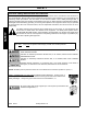
SAFETY Decal Description Multi Hazard Decal Sheet Decal D389 consists of the following multi-hazards. 2160 02/10 © 2010 Alamo Group Inc.
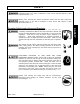
SAFETY Driveline Hazards SAFETY P/N D388 Decal D388 consists of the following multi-hazards. 2160 02/10 © 2010 Alamo Group Inc.
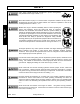
SAFETY 1000 RPM P/N D401 SAFETY WARNING! Pinch Points P/N 02962764 IMPORTANT - Service Hydraulic System with Universal Tractor Hydraulic Oil. P/N D416 DANGER! Crushing and Pinch Points. Moving machinery parts can pinch or crush or fallwhich may cause injury or death. P/N 02962765 2160 02/10 © 2010 Alamo Group Inc.
SAFETY WARNING! Tractor rearing SAFETY P/N 999001 DANGER! wings. Stay clear when lowering or raising P/N 00753840 WARNING! Failure to INSPECT and REPAIR or REPLACE Hoses may allow worn Hoses to rupture SUDDENLY and VIOLENTLY with resulting serious BODILY INJURY from SCALDING or FIRE with resulting BURN INJURY or DEATH. P/N 02965262 DANGER! - Multi-Hazard Boom. Take precautions while transporting and operating Boom Unit. P/N 02958241 2160 02/10 © 2010 Alamo Group Inc.
SAFETY For safety and to guarantee optimum product reliability always use genuine RHINO replacement parts. P/N 00760657 SAFETY Logo Product Name: Rhino P/N D303 NAME LOGO - Servis 2160 00764866 Logo Product Name: Rhino P/N D302 2160 02/10 © 2010 Alamo Group Inc.
SAFETY SAFETY Logo Name: RHINO P/N D304 INFORMATION - To prevent premature hydraulic component failure, do not over speed the engine. When using the mower attachment, operate tractor at the engine speed which will deliver 540 PTO RPM on Tachometer. Over speeding the engine and pump when operating the mower will overheat and rapidly ruin the oil which will decrease the life of the hydraulic components.
SAFETY Red Reflector. Keep reflectors clean and visible. Amber Reflector. Keep reflectors clean and visible. P/N 1458393 Slow Moving Vehicle Decal. Keep SMV reflector clean and visible. DO NOT transport or operate without the SMV. P/N 03200347 Read Operator’s Manual! The operator’s manual is located inside this canister. If the manual is missing order one from your dealer. P/N 00776031 2160 02/10 © 2010 Alamo Group Inc.
SAFETY SAFETY Information that Grease Fitting is present and must apply grease P/N 000678 2160 02/10 © 2010 Alamo Group Inc.
SAFETY Federal Laws and Regulations This section is intended to explain in broad terms the concept and effect of federal laws and regulations concerning employer and employee equipment operators. This section is not intended as a legal interpretation of the law and should not be considered as such. Employer-Employee Operator Regulations U.S. Public Law 91-596 (The Williams-Steiger Occupational and Health Act of 1970) OSHA This Act Seeks: DUTIES Sec.
INTRODUCTION SECTION Introduction Section 2-1 © 2010 Alamo Group Inc.
INTRODUCTION INTRODUCTION This Boom Mower is designed with care and built with quality materials by skilled workers. Proper assembly, maintenance, and operating practices, as described in this manual, will help the owner/operator get years of satisfactory service from the machine. The purpose of this manual is to familiarize and instruct. The Assembly Section instructs the owner/operator in the correct assembly of the Mower using standard and optional equipment.
INTRODUCTION INTRODUCTION The 2160 is ideal for mowing pond embankment levee or drainage ditches, and cutting overhanging limbs on fence rows. For Non-Agricultural use, OSHA, ASAE, SAE, and ANSI standards require the use of Chain Guards, Deflectors, or Solid Skirts at all times.
INTRODUCTION Attention Owner/Operator BEFORE OPERATING THIS MACHINE: INTRODUCTION 1. Carefully read the Operator’s Manual, completely understand the Safety Messages and instructions, and know how to operate correctly both the tractor and implement. 2. Fill out the Warranty Card in full. Be sure to answer all questions, including the Serial Number of the implement. Mail within 30 days of delivery date of this implement.
ASSEMBLY SECTION Assembly Section 3-1 © 2010 Alamo Group Inc.
ASSEMBLY TRACTOR PREPARATION ASSEMBLY 1. Move left rear tire out so that it is 50 inches minimum from the outside of left rear tire to the center of tractor. Then move the right rear tire out so that it is 96 inches minimum between the outside of the left and right rear tires. Refer to your tractor’s Operator’s Manual for instructions on Rear Wheel Adjustment for your particular tire. Asm-B-0029. Install fluid ballast inn left rear tire as needed for stability.
ASSEMBLY MOWER TO TRACTOR ATTACHMENT This mower is designed for 540 or 1000 RPM PTO with CAT II or CAT III Quick Hitch (Standard) or CAT II or CAT III 3-Point Hitch (Optional). CAT II and III Quick Hitch ( Standard) (Asm-B-0031) Back-up tractor with Quick Hitch and align bottom lugs (1) of hitch to lower lugs (2) of frame. Then raise lift arms until Pins (3) lock into lower lugs (1). Top lug (4) on Quick Hitch should simultaneously hitch to Pin (5) on top of Rhino Boom Frame.
ASSEMBLY DRIVELINE LENGTH CHECK PROCEDURE Before using mower check driveline length with tractor attached to mower. 1. Separate two halves of driveline and connect one half to tractor and the other half to mower. 2. Lower mower to normal operating position. ASSEMBLY 3. Bring the two driveline halves together as shown in figure 6. At this maximum compressed length there should be 1-1/2 inches or more clearance from tubes bottoming out. If not, shorten the driveline to obtain clearance.
ASSEMBLY HOSE CONNECTION When assembling the fittings and hoses, be careful not to introduce any dust or contaminants into the system. Keep all fittings, hoses and hydraulic components sealed until installed. Do not allow any components to lie open and exposed to dust or contamination. Do not lay parts down on the dirt or sand and then assemble them as this will introduce contaminants into the system.
ASSEMBLY ASSEMBLY ATTACHMENT OF HYDRAULIC HOSES It is important that pipe thread sealant be used only on pipe threads; never on 37 degree flared fitting or on straight thread “O” ring fittings. Use the pipe thread sealant supplied. Do not substitute with some other type of sealant, such as, teflon tape, paint, shellac, etc. Hoses supplied have two types of fittings; solid or swivel. Some hoses have solid fittings on both ends; others have a solid fitting and a swivel fitting.
ASSEMBLY HOSES TO VALVE CONNECTIONS FOR ELECTRONIC CONTROL (OPTIONAL) 2160 02/10 © 2010 Alamo Group Inc. Assembly Section 3-7 ASSEMBLY Refer to Asm-B-0032 & Asm-B-0030 and parts section page 6-24 for proper hose routing. Attach the electric valve to the plate using the two 3/8 x 5 bolts, four 3/8 flatwashers, and two 3/8 lockwashers. Connect the valve to open auxiliary hydraulic ports of the tractor. By connecting supply hoses to the valve "P1" and "P2". Both valve hoses will be p/n 02961036.
ASSEMBLY ASSEMBLY MOUNTING THE REMOTE COMMAND HANDLE The control handle is normally mounted to an existing tractor remote lever. The control handle selects one cylinder on the boom to be operated from a remote outlet. The metal bracket at the base of the control handle is mounted to the remote lever using the U-bolts and hardware included. Choose either the round U-bolts for round shafts or the flat U-bolts for flat shafts.
ASSEMBLY HOSE CONNECTIONS (DIRECT) Alternately, for a more reliable connection, this hose can be connected to a "zero back pressure" return port on the tractor. Consult your tractor's owners manual and/or tractor dealer for information regarding this type of connection. 2160 02/10 © 2010 Alamo Group Inc. Assembly Section 3-9 ASSEMBLY (Asm-B-0032) This hydraulic connection methods requires a break-away valve for the swing cylinder.
ASSEMBLY HEAD ATTACHMENT ASSEMBLY 1. Align the boom arm with the mower head lugs. Then insert main pin (1) and lock down with a 3/8 x 2 1/2 bolt (2) and a 3/8 nut. Attach linkage with 2 - 3/4 x 3 bolts (3) and lock with 2 -3/4 nuts (4). HOSE ATTACHMENT 1. Attach the 1 " hoses, from the articulating arm to the hydraulic motor on the head. Use recommended hose end torque values in chart on Section 3-5. 2160 02/10 © 2010 Alamo Group Inc.
ASSEMBLY HYDRAULIC RELIEF ATTACHMENT (OPTIONAL) (Asm-B-0037) (Required if attaching to a Non-Quick Hitch Tractor) 1. Remove the top link of the three point from the tractor. 2. Connect the center lug (1) of the Hydraulic Relief Arm (HRA) to the tractor, with the double lugs (2) up, where the top link was removed. 3. Back the tractor up to the SERVIS 2160 and connect the lower arms (3) of the three point, making sure that the HRA does not interfere with the SERVIS 2160. 4.
ASSEMBLY STARTING UNIT 1. Make sure unit has been properly assembled, all cylinders, Hoses, and the driveline have been connected. NOTE: Make sure that no materials, tools, or jacks have been left under the mower head. Make sure the front and rear of the mower are properly guarded to prevent any foreign objects from being thrown by the mower. All other workers should keep a safe distance from the unit before the mower is started. 2.
ASSEMBLY 6. Avoid hydraulic contamination by filtering the hydraulic oil while filling the hydraulic tank. Filter buggies or carts are commercially available for hydraulic system clean-up. These consist of a high-efficiency, highcapacity filter, a circulating pump, a drive motor, and hoses for connecting to the overhauled machine's hydraulic system. Asm-B-0008 & Asm-B-0009. ASSEMBLY 7. When adding hydraulic oil, use only new oil from a sealed barrel.
ASSEMBLY ASSEMBLY All Servis and Servis-Rhino Boom Mowers mounted on Non-Cab Tractors require without exception a suitable Operator Protective Cage be installed before operating to prevent Operator injury by objects thrown by the blades. The Servis Operator Protective Cage may be ordered with the machine or from the Extra Equipment Section (For your particular tractor, some modification to this Cage may be necessary.
ASSEMBLY Pre-Customer Delivery Check List 1. Is oil level in the tank even with the sight gauge on the tank? 2. Has the proper oil been used in the system? Proper oil is universal service oil or equal. 3. Does Boom machine movement match operation decal - Swing, Lift, Dipper, and Tilt? 5. Are all hoses tight and do not leak? 6. Are all decals in place? See manual for decal description and placement. 7. Have all grease points been adequately greased? 8. Are all bolts tight? 9.
OPERATION SECTION Operation Section 4-1 © 2010 Alamo Group Inc.
OPERATION RHINO 2160 BOOM MOWER OPERATION INSTRUCTIONS OPERATION Rhino 2160 boom mowers are manufactured with quality material by skilled workers. The boom is designed to attach to a tractor and operate the rotary head to cut grass and weeds. The boom and head are equipped with protective deflectors and/or chain guards to prevent objects being thrown from the mower by the blades, however, no shielding is 100% effective.
OPERATION 1. Standard Equipment and Specifications HYDRAULIC BOOM ROTARY CUTTER 60” 1-3/4” 2” 100 HP CAT II-III Q.H. 69” 71-3/8” 113” CAT 4 55 Gallons 20,028 FPM Clockwise Pan 21’ 22’, 6” 11’, 6” 3000 PSI Standard 2750 PSI 190 degrees 10 Ga. 1/4” x 9-1/4” Standard Standard 2700 lbs. with Oil EXTRA EQUIPMENT OPTIONAL EQUIPMENT Hydraulic Relief Arm Kit (For Non-Quick Hitch Tractor) 540 or 1000 RPM Electro-Hydraulic Cylinder Control Valve Kit Hyd. Valve Kit for Direct Connect (Tractors with 4-Spool Hyd.
OPERATION 2. OPERATOR REQUIREMENTS OPERATION Safe operation of the unit is the responsibility of a qualified operator. A qualified operator has read and understands the implement and tractor Operator’s Manuals and is experienced in implement and tractor operation and all associated safety practices. In addition to the safety messages contained in this manual, safety signs are affixed to the implement and tractor.
OPERATION 3. TRACTOR REQUIREMENTS The tractor used to operate the mower must have the power capacity to lift, pull, and operate the Power Take Off (PTO) at the mower’s rated speed while traveling at a ground speed between 2 and 5 MPH. Operating the mower with a tractor that does not meet the following requirements may cause tractor or mower damage and be a potential danger to the operator and passersby.
OPERATION OPERATION 3.2 Operator Thrown Object Protection The tractor must be equipped with protective equipment to shield the operator from falling and thrown objects. For cab tractors, the tractor must be equipped with an operator safety screen on its right side or the right side windows must be fitted with a shatter proof safety window. For non-cab tractors, the tractor must be equipped with a ROPS and operator protective safety cage that provides protection to the right and above the operator seat.
OPERATION 3.4 Tractor Ballast For additional information on properly ballasting the tractor, refer to Alamo Industrial Tractor and Mower Stability Pamphlet P/N #02959010 If the unit is operated on slopes greater than 5°, additional counterweight will be required. Operation of the unit on slopes greater than 11 percent (6.4 degrees) is not recommended under any circumstances. On a tractor with a 96” outside to outside tire spread, an 11 percent (6.
OPERATION 3.6 Front End Weight A minimum of 20% total tractor weight must be maintained on the tractor front end at all times. Front end weight is critical to maintain steering control and to prevent the tractor from rearing up while driving. If the front end is too light, add weight until a minimum of 20% total weight is reached on the front tires. Front weights and weight carriers can be purchased through an authorized tractor dealership. OPS-U- 0005 OPERATION 3.
OPERATION 4.1 Boarding the Tractor Use both hands and equipped handrails and steps for support when boarding the tractor. Never use control levers for support when mounting the tractor. Seat yourself in the operator’s seat and secure the seat belt around you. Never allow passengers to ride on the tractor or attached equipment. Riders can easily fall off and be seriously injured or killed from falling off and being ran over. It is the operator’s responsibility to forbid all extra riders at all times.
OPERATION 5. STARTING THE TRACTOR The operator must have a complete understanding of the placement, function, and operational use of all tractor controls before starting the tractor. Review the tractor operator’s manual and consult an authorized dealer for tractor operation instructions if needed.
OPERATION 6. SETTING THE MOWER Properly setting the cutting height is essential for efficient and safe operation. A properly set mower will make a more uniform cut, distribute clippings more evenly, require minimal tractor work, and follow the contour of uneven terrain. NOTE: Avoid very low cutting heights, striking the ground with the blades gives the most damaging shock loads and will cause damage to the mower and drive.
OPERATION Never work under the Implement, the framework, or any lifted component unless the Implement is securely supported or blocked up to prevent sudden or inadvertent falling which could cause serious injury or even death. (SG-14) OPERATION Periodically inspect all moving parts for wear and replace when necessary with authorized service parts. Look for loose fasteners, worn or broken parts, and leaky or loose fittings. Make sure all pins have cotter pins and washers.
OPERATION 7.1 Tractor Pre-Operation Inspection/Service Refer to the tractor operator’s manual to ensure a complete pre-operation inspection and scheduled service is performed according to the manufacturers recommendations.
OPERATION FRAME ASSEMBLY • • • • OPERATION • Inspect condition of mounting frame weldment. Inspect condition of King Post frame. Ensure all bolts and screws are in position and are properly torqued. Ensure all pins are in place and fastened with screws. Ensure frame is properly mounted to tractor and hardware is propely installed and tightened. OPS-B- 0021_E BOOM ARM ASSEMBLY • • • • • Inspect condition of each arm section weldment Ensure all pins are in place.
OPERATION HYDRAULIC LINE INSPECTION • • • • Do not operate this Equipment with hydraulic oil or fuel leaking. Oil and fuel are explosive and their presence could present a hazard. Do not check for leaks with your hand! High-pressure oil streams from breaks in the line could penetrate the skin and cause tissue damage including gangrene. To check for a hose leak, SHUT the unit ENGINE OFF and remove all hydraulic pressure.
OPERATION OPERATION HYDRAULIC PUMP/OIL RESERVOIR • Check oil reservoir level and oil condition. (Add specific type oil if low) • Change hydraulic oil filter and hydraulic oil according to maintenance schedule. • Ensure there are no oil leaks and fitting are properly connected • Inspect overall condition of hydraulic pump. • Inspect pump drive shaft. Check the fluid level in the Hydraulic Tank on the Tractor, and add oil if required.
OPERATION ROTARY HEAD INSPECTION • • • • Do not put hands or feet under mower decks. Blade Contact can result in serious injury or even death. Stay away until all motion has stopped and the decks are securely blocked up. (SGM-09) 2160 02/10 © 2010 Alamo Group Inc. Operation Section 4-17 OPERATION • Inspect blades and blade bolts for looseness and excessive wear. Rotate to 90° to make for checking easier. Replace damaged, worn, and missing blades as complete sets to maintain rotary balance.
OPERATION 40 7.3 Cutting Component Inspection OPERATION Inspect blade pan and blade assembly for the following: OPS-U-0031 2160 02/10 © 2010 Alamo Group Inc.
OPERATION Operating the mower with loose blade hardware will damage the blade holder or blades and can result in blade breakage or blade fastener failure. Broken blades or bolts can be thrown out from under the mower for distances up to 300 feet. When the blades are replaced, the fastening hardware must be replaced. Check and retighten the blade hardware after the first eight hours of operation. In severe cutting conditions, recheck the blade carrier and blade bolt torque every 50 hours.
OPERATION 7.4 Blade Bolt Inspection OPERATION Inspect Blade Bolt Head daily for wear as followed: Inspect the Blade Bolt Heads daily for abnormal wear. REPLACE BOTH BLADE BOLTS on the Blades IMMEDIATELY if either blade bolts has: • Visible cracks or • If the recessed area on blade bolt is worn off or • If Blade Bolt has gouges or chipped areas.
OPERATION Tractor PRE-OPERATION Inspection Tractor ID#________________ Make ____________________ Date: Shift ________________ ____________________ Condition at Start of Shift Item Specific Comments if not O.K.
OPERATION OPERATION Boom Mower PRE-OPERATION Inspection Mower ID#________________ Make ____________________ Date: Shift ________________ ____________________ Before conducting the inspection, make sure the tractor engine is off, all rotation has stopped and the tractor is in park with the parking brake engaged. Make sure the mower is resting on the ground or securely blocked up and all hydraulic pressure has been relieved. Condition at Start of Shift Item Specific Comments if not O.K.
OPERATION 8. DRIVING THE TRACTOR AND IMPLEMENT Safe tractor transport requires the operator possess a thorough knowledge of the model being operated and precautions to take while driving with an attached implement. Ensure the tractor has the capacity to handle the weight of the implement and the tractor operating controls are set for safe transport. To ensure safety while driving the tractor with an attached implement, review the following.
OPERATION 8.1 Starting the Tractor OPERATION The procedure to start the tractor is model specific. Refer to the tractor operator’s manual for starting procedures for your particular tractor. Consult an authorized dealer if the starting procedure is unclear. Ensure the 3-point control lever is in the lowered position and the PTO is disengaged before starting the tractor. OPS-U-0033 Start tractor only when properly seated in the Tractor seat. Starting a tractor in gear can result in injury or death.
OPERATION 8.3 Driving the Tractor and Boom Inspect the area to be mowed before beginning operation. Identify any drop-offs, slopes, holes, hidden obstructions or similar obstacle that could cause the tractor to loose stability and potential roll-over. Mark and avoid the item or the entire area. Start off driving at a slow speed and gradually increase your speed while maintaining complete control of the tractor.
OPERATION 9. OPERATING THE TRACTOR AND IMPLEMENT OPERATION THE OPERATOR MUST COMPLETELY UNDERSTAND HOW TO OPERATE THE TRACTOR AND IMPLEMENT AND ALL CONTROLS BEFORE ATTEMPTING TO OPERATE. The operator must read and understand the Safety and Operation Sections of the implement and tractor operator’s manuals. These manuals must be read and explained to any operator who cannot read. Never allow someone to operate the implement and tractor without complete operating instructions.
OPERATION Use extreme care and Safety Awareness when using the boom mower head to mulch loose brush or wood that has fallen on the ground from overhead trimming. DO NOT mulch this debris if bystanders, vehicles, livestock or buildings are within 300 feet of the mower. This cut debris can be thrown at great velocities and could result in serious injury or even death. (SBM-17) Many varied objects, such as wire, cable, rope, or chains, can become entangled in the operating parts of the mower head.
OPERATION OPERATION The mower valve comes with a push-pull operator switch that, when properly installed, will prevent the tractor from starting if the switch is in the ON position (pulled out). To properly install the push-pull operator, follow the wiring diagram shown. Failure to properly install this switch could result in injury to the operator or bystander. Operate the Tractor and/or Implement controls only while properly seated in the Tractor seat with the seat belt securely fastened around you.
OPERATION The valves and their use will be explained in the following pages of this manual. Read each explanation carefully then practice in a safe, level area, CLEAR of all people, animals, and any obstructions. As always, use extreme caution when using this machine. This valve is controlled by operating the Remote Control Valve Box mounted to the right of the operator at a convenient height. NOTE: The stamped metal plate located above the control valve indicates each valve function.
OPERATION 9.3 Operating Speed and Ground Speed OPERATION Ground speed for mowing will depend upon the height, type, and density of vegetation to be cut. Do Not exceed 2 MPH while operating. Operate the mower at its full rated PTO speed to maintain blade speed for a clean cut. Refer to the tractor operator’s manual or the tractor instrument panel for the engine speed and gear to provide the required operating and desired ground speed.
OPERATION Rotary Cutter • • • The rotating parts of this machine have been designed and tested for rugged use. However, the blades could fail upon impact with heavy, solid objects such as metal guard rails and concrete structures. Such impact could cause the broken objects to be thrown outward at very high velocities. To reduce the possibility of property damage, serious injury, or even death, never allow the cutting blades to contact such obstacles.
OPERATION 9.5 Shutting Down the Attached Head OPERATION To shut down attached boom head, first bring the tractor to a complete stop. Keep the engine speed at normal operating speed of 540 RPM, and push the Motor Switch IN to the Stop position. The mower head will come to a complete stop with in 15 seconds.
OPERATION DETACHING AND STORING 10.1 Quick - Hitch 1. 2. 3. 4. 5. Swing the mower head to the rear. Place mower head on the ground. Make sure dipper section is vertical. Disconnect PTO. Level the frame by adjusting the boom. Lower the stands onto the ground. 6. Disengage the locking mechanism on the quick hitch. 7. Lower the 3-point hitch arms until quick hitch comes off the frame. 10.2 Hydraulic Relief Arm 1. 2. 3. 4. 5. 6. 7. 8. Swing the mower head to the rear. Place the mower head on the ground.
OPERATION Never allow children to play on or around Tractor or Implement. Children can slip or fall off the Equipment and be injured or killed. Children can cause the Implement to shift or fall crushing themselves or others. (SG-25) OPERATION 11. TRANSPORTING THE TRACTOR AND IMPLEMENT Inherent hazards of operating the tractor and implement and the possibility of accidents are not left behind when you finish working in an area.
OPERATION Before transporting tractor between locations, idle the tractor engine, disengage the attached head, and wait for all head motion to come to a complete stop. Place the boom in its storage cradle rest support and then turn the joystick master switch to the OFF position. Placing Boom Articulating Arm on Boom Arm Rest • Before transporting the tractor on a public roadway or boarding a trailer for transport, the tractor brake pedals should be locked together.
OPERATION 11.1 Transporting on Public Roadways OPERATION Extreme caution should be used when transporting the tractor and implement on public roadways. The tractor must be equipped with all required safety warning features including a SMV emblem and flashing warning lights to alert drivers of the tractor’s presence. Remember that roadways are primarily designed for automotive drivers and most drivers will not be looking out for you, therefore, you must look out for them.
OPERATION Make sure that all tractor flashing warning lights, headlights, and brake/tail lights are functioning properly before proceeding onto public roads. While newer model tractors have plenty of lighting to provide warning signals and operating lighting, most older models are only equipped with operating lights. Consult an authorized tractor dealer for lighting kits and modifications available to upgrade the lighting on older tractor models.
OPERATION OPERATION Reduce speed before turning or applying the brakes. Ensure that both brake pedals are locked together when operating on public roads. OPS-U- 0023 11.2 Hauling the Tractor and Implement Before transporting a loaded tractor and implement, measure the height and width dimensions and gross weight of the complete loaded unit. Ensure that the load will be in compliance with the legal limits set for the areas that will be traveled through.
OPERATION Arrange the chains so that when tightened, the chains are pulling downward and against themselves. Carefully tighten the securing chains or other fasteners using boomers or binders to apply maximum tension. Use extreme care when attaching and removing the securing devices as the extreme tension involved when released has the potential to inflict serious injury. 12. TROUBLESHOOTING GUIDE A. HYDRAULIC CYLINDER NOT WORKING - Check level of hydraulic fluid (see sight gauge on tank).
MAINTENANCE SECTION Maintenance Section 5-1 © 2010 Alamo Group Inc.
MAINTENANCE Before operating the 2160, make sure it is properly lubricated and thoroughly inspected. Only a minimum of time and effort is required to regularly lubricate and maintain this machine to provide long life and trouble free operation. MAINTENANCE Always disengage the PTO before raising the Rotary Cutter for transporting or making adjustments. LUBRICATION INFORMATION Do not let excess grease collect on or around parts, particularly when operating in sandy areas.
MAINTENANCE DRIVELINE LUBRICATION Grease Fittings are located on the Cross Assembly of each U-Joint and on the telescoping tubes. Grease the U-Joint after each 8 hours of use. Mnt-0024. Do not force grease through the Needle Cup Assemblies. Grease the telescoping tubes after every 8 hours use. Some PTO-to-Hitch connections may necessitate cutting a hole in the shields to be able to align the Grease Fitting holes for lubrication. Lubricate the shield bearings every 16 hours.
MAINTENANCE MAIN DRIVELINE & CAT 4 SAFETY SHIELD MAINTENANCE To remove the main inner driveline shield. Remove the locking screws. Align the bearing tabs with the cone pockets. Mnt-B-0043. Remove the half-guard and remove the bearing ring. Mnt-B-0044. Inspect the driveline shield for worn areas or cracks. If the shield has any dents or cracks, replace the Shield. While the Shields are off, examine the Driveline for signs of abnormal wear, bent or twisted shafts, or cracks in the shafts or tubes.
MAINTENANCE Make certain that the Driveline Integral Shields are free to telescope and rotate around the Driveline without binding. MAINTENANCE 2160 02/10 © 2010 Alamo Group Inc.
MAINTENANCE HYDRAULIC OIL, FILTERS AND COMPONENTS MAINTENANCE Filters and Oil - Change the return tank filter and suction filters after the first 200 hours of operation. Change the filters again at 800 hours; then, change the oil and filters at 1600 hours. After that, continue to change the filter every 800 hours and the oil every 1600 hours. Hydraulic oil to be universal service or equal. Speed Increaser uses Multi-Purpose Gear Oil P/N 00786250 and the spindle uses N.L.G.I. #2 grease.
MAINTENANCE BLADES Check the Blade for cracks and wear and Blade Bolts for tightness, daily. Blades should be replaced when they are worn excessively, bent, deformed, or out of balance. Blades should always be replaced in pairs. Blades of different weights can cause serious imbalance and damage to the machine and personnel. When replacing blades, take care to replace the bolts, nuts and washers. Most nuts and bolts will stay tight and therefore need only periodic checking.
MAINTENANCE BLADE SHARPENING Always sharpen both blades at same time to maintain balance. Follow original sharpening pattern as shown in FIGURE Mnt-R-0008. Always sharpen blades by grinding. DO NOT heat and pound out edge. Do not sharpen blade to a razor edge, but leave a 1/16" blunt edge. Do not sharpen back side of blade. MAINTENANCE Avoid personal injury. Always block the cutter up to prevent if from falling when the blades and/or carrier are being serviced. Avoid personal injury.
MAINTENANCE BLADE CARRIER REMOVAL Remove cotter pin and loosen slotted nut on spindle shaft. Loosen but do not remove the nut until the blade carrier is loosened. Use long bar inserted through blade bolt access hole with the end against rotor bar. Strike opposite end of bar with sledge hammer. Rotate blade carrier 180 degrees and repeat process.
MAINTENANCE BLADE CARRIER INSTALLATION Clean the taper on both the blade carrier and output shaft. Position carrier on the gearbox output shaft and install special washer nut. Tighten nut, while holding blade carrier, to minimum 450 ft./lbs. strike the carrier near the hub several times with a heavy hammer to seat the hub. Use a suitable spacer over the nut to prevent damage to the nut and threads. Retighten the nut to 450 ft./lbs. Install cotter pin and spread.
MAINTENANCE STORAGE Your rotary mower represents an investment from which you should get the greatest possible benefit. Therefore, when the season is over, the cutter should be thoroughly checked and prepared for storage so that a minimum amount of work will be required to put it back into operation for the next season. The following are suggested storage procedures: Thoroughly clean the cutter. Lubricate the cutter as covered in Maintenance Section. Tighten all bolts and pins to the recommended torque.
RHINO LIMITED WARRANTY 1. 2. LIMITED WARRANTIES 1.01. Rhino warrants for one year from the purchase date to the original non-commercial, governmental, or municipal purchaser (“Purchaser”) and warrants for six months to the original commercial or industrial purchaser (“Purchaser”) that the goods purchased are free from defects in material or workmanship. 1.02.
TO THE OWNER/OPERATOR/DEALER To keep your implement running efficiently and safely, read your manual thoroughly and follow these directions and the Safety Messages in this Manual. The Table of Contents clearly identifies each section where you can easily find the information you need. The OCCUPATIONAL SAFETY AND HEALTH ACT (1928.51 Subpart C) makes these minimum safety requirements of tractor operators: REQUIRED OF THE OWNER: 1.
2160 BOOM ROTARY MOWER 2160-SOM-02/10 Printed U.S.