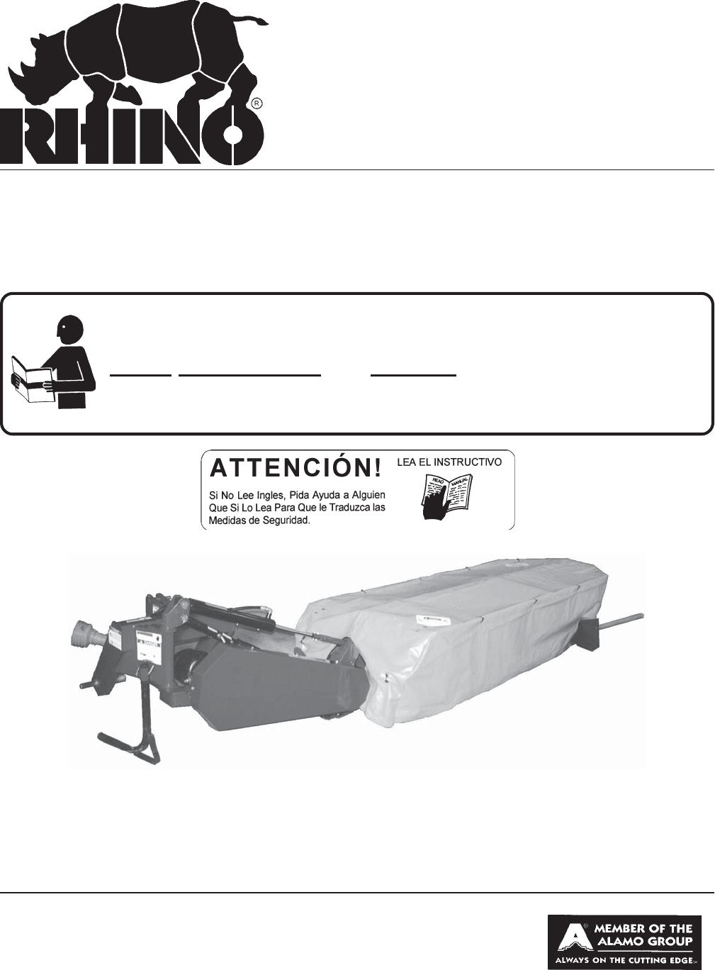
DISC MOWER DM82, DM95, DM112 & DM124 Disc Mower Published 04-14-03 Effective S/N DM82 20000- Current Effective S/N DM95 20201- Current Part No.4909WC OPERATOR'S MANUAL This Operator's Manual is an integral part of the safe operation of this machine and must be maintained with the unit at all times. READ, UNDERSTAND, and FOLLOW the Safety and Operation Instructions contained in this manual before operating the equipment. OPERATOR'S MANUAL RHINO® 1020 S. Sangamon Ave.
TO THE OWNER/OPERATOR/DEALER All implements with moving parts are potentially hazardous. There is no substitute for a cautious, safe-minded operator who recognizes the potential hazards and follows reasonable safety practices. The manufacturer has designed this implement to be used with all its safety equipment properly attached to minimize the chance of accidents. BEFORE YOU START!! Read the safety messages on the implement and shown in your manual.
BE SAFE! BE ALERT! BE ALIVE! BE TRAINED before operating the Mower! Safety Training Makes the Difference In order to reduce accidents and enhance the safe operation of mowers, Alamo Group Ag Division, in cooperation with other industry manufacturers has developed the AEM/FEMA Industrial and Agricultural Mower Safety Practices video and guide book. The video will familiarize and instruct mower-tractor operators in safe practices when using industrial and agricultural mowing equipment.
Alamo Group Ag.
TABLE OF CONTENTS SAFETY SECTION ......................................................................................................................................... 1-1 Safety Information ........................................................................................................................................... 1-2 Decal Location ..............................................................................................................................................
TABLE OF CONTENTS When ordering parts for this manual be sure that orders for replacement parts include the following information: 1. Name of machine 2. Machine model number 3. Machine serial number (The serial number plate is located on the front of the 3-point frame) 4. Quantity of part required 5. Rhino part number (from manual) 6.
SAFETY SECTION Safety Section 1-1
SAFETY A safe and careful operator is the best operator. Safety is of primary importance to the manufacturer and should be to the owner/operator. Most accidents can be avoided by being aware of your equipment, your surroundings, and observing certain precautions. The first section of this manual includes a list of Safety Messages that, if followed, will help protect the operator and bystanders from injury or death.
SAFETY PELIGRO! Si no lee Ingles, pida ayuda a alguien que si lo lea para que le traduzca las medidas de seguridad. (SG-3) DANGER! Never operate the Tractor or Implement until you have read and completely understand this Manual, the Tractor Operator’s Manual, and each of the Safety Messages found in the Manual or on the Tractor and Implement. Learn how to stop the tractor engine suddenly in an emergency.
SAFETY DANGER! Never allow children or other persons to ride on the Tractor or Implement. Falling off can result in serious injury or death. (SG-10) DANGER! Never allow children to operate or ride on the Tractor or Implement. (SGM-11) WARNING! Do not mount the Tractor while the tractor is moving. Mount the Tractor only when the Tractor and all moving parts are completely stopped. (SG-12) DANGER! Start tractor only when properly seated in the Tractor seat.
SAFETY WARNING! Transport only at safe speeds. Serious accidents and injuries can result from operating this equipment at unsafe speeds. Understand the Tractor and Implement and how it handles before transporting on streets and highways. Make sure the Tractor steering and brakes are in good condition and operate properly. Before transporting the Tractor and Implement, determine the safe transport speeds for you and the equipment. Make sure you abide by the following rules: 1.
SAFETY DANGER! DANGER! WARNING! DANGER! KEEP AWAY FROM ROTATING ELEMENTS to prevent entanglement (SG-24) and possible serious injury or death. Never allow children to play on or around Tractor or Implement. Children can slip or fall off the Equipment and be injured or killed. Children can cause the Implement to shift or fall crushing themselves or others. (SG-25) Do not exceed the rated PTO speed for the Implement.
SAFETY DANGER! All Safety Shields, Guards and Safety devices including (but not limited to) - the Deflectors, Chain Guards, Steel Guards, Gearbox Shields, Hydraulic Tank Shields, and Retractable Door Shields should be used and maintained in good working condition. All safety devices should be inspected carefully at least daily for missing or broken components.
SAFETY DANGER! Replace bent or broken blade with new blades. NEVER ATTEMPT TO STRAIGHTEN BLADES SINCE THIS WILL LIKELY CRACK OR OTHERWISE DAMAGE THE BLADE WITH SUBSEQUENT FAILURE AND POSSIBLE SERIOUS INJURY FROM THROWN BLADES. (SGM-10) WARNING! Do not mow with two machines in the same area except with Cab tractors with the windows closed. (SGM-11) DANGER! Always disconnect the main PTO Driveline from the Tractor before performing service on the Mower.
SAFETY WARNING! Never leave Tractor and Implemented unattended while the implement is in the lifted position. Accidental operation of lifting lever or a hydraulic failure may cause sudden drop of unit with injury or death by crushing. To properly park the implement when disconnecting it from the tractor, lower the stand and put the retaining pin securely in place, or put a secure support under the AFrame. Lower the implement carefully to the ground. Do not put hands or feet under lifted components.
SAFETY In addition to the design and configuration of this Implement, including Safety Signs and Safety Equipment, hazard control and accident prevention are dependent upon the awareness, concern, prudence, and proper training of personnel involved in the operation, transport, maintenance, and storage of the machine. Refer also to Safety Messages and operation instruction in each of the appropriate sections of the Tractor and Equipment Manuals.
SAFETY NOTES DM 07-02 © 2004 Alamo Group Inc.
SAFETY NOTE: Rhino supplies safety decals on this product to promote safe operation. Damage to the decals may occur while in shipping, use, or reconditioning. Rhino cares about the safety of its customers, operators, and bystanders, and will replace the safety decals on this product in the field, free of charge (Some shipping and handling charges may apply). Contact your Rhino dealer to order replacement decals. 27 30 31 32 27 29 28 DM 07-02 © 2004 Alamo Group Inc.
SAFETY ITEM 1 2 3 4 5 6 7 8 9* 10 11 12 13 14 15 16 17 18 19 20 21 22 23 24 25 26 27 28 29 30 31 32 PART NO. QTY.
SAFETY 1 - 00725746 5 - 00760657 2 - 00756004 4 - 00756494 3 - 00756005 6 - 02962765 DM 07-02 © 2004 Alamo Group Inc.
SAFETY 10 - 3238320 8 - 3238318 9 - 3238319 12 - 00756059 11 - 999001 17 - 1458380 15 - 00763977 21 - 3238307 25 - D301 7 - 3238322 - Front Cover 13 - 00758194 DM 07-02 © 2004 Alamo Group Inc.
SAFETY 14 - 3238311 18 - 00772879 19 - 3238300 20 - 3238301 DM82 DM95 23 - 00772632 23 - 00772631 DM112 DM124 23 - 00772633 DM 07-02 © 2004 Alamo Group Inc.
SAFETY 22 - D103 26 - 2458315 27- 00776481 DM 07-02 © 2004 Alamo Group Inc.
SAFETY FEDERAL LAWS AND REGULATIONS This section is intended to explain in broad terms the concept and effect of federal laws and regulations concerning employer and employee equipment operators. This section is not intended as a legal interpretation of the law and should not be considered as such. Employer-Employee Operator Regulations U.S. Public Law 91-596 (The Williams-Steiger Occupational and Health Act of 1970) OSHA This Act Seeks: “...
INTRODUCTION SECTION Introduction Section 2-1
INTRODUCTION This Mower is designed with care and built with quality materials by skilled workers. Proper assembly, maintenance, and operating practices, as described in this manual, will help the owner/operator get years of satisfactory service from the machine. The purpose of this manual is to familiarize, instruct, and train. The Safety Section is a MUST READ section prior to any use of the mower.
ASSEMBLY SECTION Assembly Section 3-1
ASSEMBLY CAUTION! WEAR PROPER PROTECTIVE EQUIPMENT SUCH AS SAFETY GLASSES AND PROTECTIVE SHOES WHEN ASSEMBLING THE MOWER. USE OVERHEAD CRANE OR HOIST. See pages 6-1 through 6-22 in the Parts List Section and identify the components to be installed. When the instructions refer to the left or right side, they refer to your left or right side, as you are standing behind the mower and facing the tractor. Refer to Torque Chart on Page 5-6 for correct torque on all bolts.
ASSEMBLY 6. Connect the break away tongue to the frame using a break away pin and cotter keys(E). (See Figure 4.) Figure 4 7. Install the cover frame on the cutter bar using two M16 x 35mm bolts (F), locking plate and lockwashers at the top and three M16x35mm bolts and lockwashers (G) installed on the side. (See Figure 5.) Torque the M16 bolts to 100 FT-LBS. Use a thread-locking compound on top of 16mm bolts.(Note: Included with kit is a packet of locktight.) 8.
ASSEMBLY 9. Place the cover sheet over the assembled frame and secure the sheet in place with plastic ties through grommets around cover frame at all locations. (See Figure 7.) DO NOT OVERTIGHTEN PLASTIC TIE. 10. Attach the hydraulic cylinder and Lift Rod (K) to the main frame and link attached to the cover frame. Use a lift rod pin, capscrew and lockwasher. To secure the lift rod to the link and a cylinder pin and cotter keys to secure the cylinder to the main frame yoke. (See Figure 8.
ASSEMBLY 14. Attach the outer support weldment to the swath board bracket and the cover frame tube as shown (Figure 11&12).Using two M10 x 75 mm bolts and locknuts on top (O), and one M12 x 50mm bolt (N), and one M12 x 50mm carriage bolt (M). 15. Install the outer tarp support spring to the rear cover frame (P) as shown (Figure 13). Figure 11 Figure 12 Figure 13 DM 07-02 © 2004 Alamo Group Inc.
ASSEMBLY 16. To check the oil level, tilt the cutter bar up 90 degrees and remove Plug(L) . Add SAE EP90 gear lube, or equivalent, at opening until oil flows from opening . Reinstall plug. Use thread sealant on plug threads. (See Figure 14 & 15). The following approximate amounts of SAE EP90 gear lubricant, or equivalent, are required: Model DM82 ................. 2.4 Quarts Model DM95 ................. 3.1 Quarts Model DM112 ................ 3.8 Quarts Model DM124 ............... 4.
OPERATION SECTION Operation Section 4-1
OPERATION The Rhino Disc Mower requires 540 RPM PTO power and is designed to mount on Category II 3-point hitch equipped tractors. Model DM82 mowers require a minimum of 40 HP for operation. Model DM95 mowers require a minimum of 45 HP. Model DM112 mowers require a minimum of 50 HP. Model DM124 mowers require a minumum of 60 HP. Connecting the Mower to the Tractor 1. Connect the 3-point frame to the lower links of the tractor and secure with klick pins.
OPERATION 6. Lower the mower so that the center of the lower linkage arm is 16" above the ground. (See Figure 5.) 7. Connect the Support chain (S) to the tractor's top link support bracket and adjust to maintain the ground-tolinkage height of 16" set in Step in 5. Plate attaches on righthand lower lift arm pin. Chain should maintain mower height, adjust as necessary. 8. Lower the mower to the ground and check the following: A. Cutter bar contact with the ground. B. Proper chain tension. C.
OPERATION IID Shaft Installation Adjusting Shaft Length (Con't) 4. Cut the shield and shaft of the mower half so the same amount is removed as the tractor half. Deburr the ends, lubricate the shaft halves with grease and reassemble the halves. 5. Install the IID shaft on the tractor and mower. Raise and lower the mower to check for shaft contact (bottoming-out) with the mower yoke end. At the maximum compressed point, the shaft should look like Figure 9.
OPERATION Adjusting Mowing Height The mowing height is adjusted by adjusting the top link of the 3-point linkage to move the forward portion of the disc up or down. (See Figure 11.) IMPORTANT: Do not allow the disc blade to contact the ground. On uneven ground, raise the blade tip by tilting the cutter rearward. Tipping the cutter too far rearward, over horizontal will result in premature blade wear. Cutting too close to the ground will cause excessive blade wear.
OPERATION BELT TENSION ADJUSTMENT The belt tension must be adjusted properly to prevent the belt from slipping. To adjust the belt tension, loosen the jam nut and tighten the nuts on the Tensioning Rod until each belt can be depressed 1/2" when a force of 11 pounds is applied to the belt at a point midway between the pulleys (See Figure 14). An Access Hole (V) is provided in the belt shield to check belt tension (See Figure 15).
OPERATION Swath Board The Swath Board (W) is located on the outer end of the cutter bar. The swath stick can be positioned at three settings to handle different crop conditions such as long, short or flattened crops. Remove the front bolt (Y), move the swath stick to the desired position and reinstall the bolt in the new hole. (See Figure 17.
OPERATION TRANSPORTING THE MOWER 1. Make sure the stand tube is secured in the "up" position. If not, pull clip and Pin (R) and slide Stand Tube (A) up. Secure with Pin (R) and clip. (See Figure 19.) A R Figure 19 2. Before folding check clearance between tractor & cover frame. Fold back the front cover frame (H) and cover sheet. (See Figure 20.) Fold front & rear cover under front cover frame and secure with tarp strap stored under center of rear cover. Attach to hole in center front cover frame.
OPERATION 3. Remove the Lock Pin (Y) from the suspension tube. After raising the bar to the transport position, move the lock pin to transport position and secure with hairpin cotter. (See Figure 21) Figure 21 J Figure 22 TRANSPORT LOCK STORAGE 4. Raise the cutter bar using the tractor hydraulics. (See Figure 23). 5.
OPERATION WARNING! DISC MOWERS ARE NOT INTENDED FOR ROADSIDE OR MUNICIPAL MOWING. THEY ARE INTENDED FOR AGRICULTURAL USE ONLY. DO NOT OPERATE MOWER NEAR STRUCTURES WHICH MAY BE VULNERABLE TO DAMAGE FROM THROWN OBJECTS. THE OPERATING TRACTOR SHOULD BE EQUIPPED WITH AN ENCLOSED CAB! CAUTION! BEFORE STARTING OPERATION, MAKE SURE THE COVER SHEET IS IN GOOD SHAPE AND IN THE LOWERED POSITION.
OPERATION CAUTION! STOP MOWER IMMEDIATELY IF IT BEGINS TO VIBRATE. OPERATING THE MOWER WITH A VIBRATION MAY RESULT IN COMPONENT FAILURE. DETERMINE CAUSE OF VIBRATION AND CORRECT. CHECK IF KNIVES ARE IN GOOD CONDITION AND ROTATING FREELY. WIRE OR TWINE WHICH BECOMES ENTANGLED AROUND DISC SHOULD BE REMOVED IMMEDIATELY AS IT MAY RESULT IN SEAL OR DISC BEARING FAILURE. REPLACE WORN OR BENT KNIVES. REPLACE KNIVES IN PAIRS ONLY ON EACH DISC. REPLACING ONLY ONE KNIFE WILL CAUSE UNBALANCE.
MAINTENANCE SECTION Maintenance Section 5-1
MAINTENANCE CAUTION! BEFORE PERFORMING INSPECTIONS, MAINTENANCE, OR ADJUSTMENTS OF THE MOWER, STOP THE TRACTOR ENGINE, REMOVE THE KEY, AND SECURE PARKING BRAKE. WAIT FOR ALL ROTATING MOTION OF THE MOWER TO STOP AND DISCONNECT THE DRIVELINE SHAFT. BLOCK THE MOWER AND TRACTOR TO PREVENT MOVEMENT BEFORE PERFORMING ADJUSTMENTS OR MAINTENANCE. WARNING! AFTER MAINTENANCE OR ADJUSTMENTS ARE COMPLETED, REMOVE ALL BLOCKS AND TOOLS USED IN MAINTENANCE OR ADJUSTMENTS.
MAINTENANCE Figure 2 To remove the disc, remove the 6 bolts (DD)(See Figure 1). To remove the hub (EE), remove the locknut (FF) and the conical washer (GG). Pull the hub upward evenly to remove. Gearpullers may be required to remove hub from spline shaft. See Figure 3 EE FF GG Make sure the Conical Spring Washer (EE) is placed on the shaft before the disc retaining nut is installed. Place the washer on the shaft with the center up.
MAINTENANCE LUBRICATION Both the gearbox and the cutter bar are lubricated by a seperate oil supply. To fill the cutter bar. Raise the cutter bar up 90 degrees and remove Plug. Add SAE HD90 gear lube or equivalent until oil flows from opening. Reinstall the plug using a pipe thread sealant. (See Figure 4 & 5.) Figure 5 Figure 4 The following approximate amounts of SAE HD90 gear lube, or equivalent, are required: Model DM82 2.4 Quarts Model DM95 3.1 Quarts Model DM112 3.8 Quarts Model DM124 4.
MAINTENANCE GEARBOX SECTION END VIEW Bolt 61367C8 Plug 00772811 Oil Filler PLug 2716591 Bolt 708110C12 Bolt 708110C12 Hex Nut 00756164 Hex Nut 00756164 CUTTERBAR SECTION END VIEW DM 07-02 © 2004 Alamo Group Inc.
MAINTENANCE Lubrication Chart Location 1 2 3 4 5 6 7 Description Front IID U-joint Rear IID U-joint IID Shaft Slip Joints Gearboxes and Cutter Bar, Fill to respective Level Plug w/SAE EP90 or Equivalent Gear Lube Main Frame Pivot Point All Sliding Sections All Pivots & Linkage Lubrication Frequency After Every 8 Hours of Operation After Every 8 Hours of Operation After Every 8 Hours of Operation Check Level After Every 8 Hours of Operation Daily After Every 8 Hours of Operation After Every 8 Hours of Oper
MAINTENANCE Storage To prepare your Disc Mower for storage: 1. Clean the mower of all dirt and debris. 2. Drain the oil from the cutter bar and replace with fresh SAE HD90 lube oil. (See Lubrication Instructions.) 3. Store the mower on a clean, dry surface in the down (working) position. 4. Loosen the drive belts or remove the belts and store in a dry place. 5. Lubricate all points and slides before storage. This prevents corrosion.
MAINTENANCE Specifications Model Width of Cut Number of Discs Number of Blades Speed of Discs at 540 RPM Peripheral Speed of Blades Working Speed Recommended Tractor HP Range Cutter bar Lift Cutter bar Protection IID Shaft Linkage Approximate Weight Cutter bar Safety Regulation Guards Spring Assist CAUTION! DM82 6'9" 5 10 DM95 DM112 DM124 8' 9'4" 10'3" 6 7 8 12 14 16 3000 Revolutions Per Minute (RPM) 256 Feet Per Second 4-6 Miles Per Hour (MPH) 45-70 HP 50-75 HP 75-90HP 75-95HP Single Acting Hydraulic Cy
SERVIS-RHINO LIMITED WARRANTY 1. LIMITED WARRANTIES 1.01.Servis-Rhino warrants for one year from the purchase date to the original non-commercial, governmental, or municipal purchaser (“Purchaser”) and warrants for six months to the original commercial or industrial purchaser (“Purchaser”) that the goods purchased are free from defects in material or workmanship. 1.02.
TO THE OWNER/OPERATOR/DEALER To keep your implement running efficiently and safely, read your manual thoroughly and follow these directions and the Safety Messages in this Manual. The Table of Contents clearly identifies each section where you can easily find the information you need. The OCCUPATIONAL SAFETY AND HEALTH ACT (1928.51 Subpart C) makes these minimum safety requirements of tractor operators: REQUIRED OF THE OWNER: 1. 2. 3. 4.
DISC MOWER DM82, DM95, DM112 & DM124 Disc Mower DISC MOWER-OM 07/02 Printed U.S.A.
An Alamo Group Company SERVIS-RHINO® 1020 S. Sangamon Ave. Gibson City, IL 60936-9907 Please fold (do not tear), tape, and drop in any mailbox. PLEASE FILL OUT OWNER WARRANTY REGISTRATION INFORMATION SIGN, AND DROP LAST COPY IN ANY MAILBOX. IMPORTANT! TO PLACE THIS WARRANTY IN EFFECT, THIS WARRANTY REGISTRATION MUST BE FILLED OUT, SIGNED, AND MAILED WITHIN 30 DAYS OF DELIVERY DATE OF THIS MACHINE. DEALER AND PURCHASER MUST SIGN.
SERVIS-RHINO WARRANTY REGISTRATION INFORMATION MONTH Servis-Rhino Model Serial No. DAY YEAR Purchase Date Purchaser Last Name Street & No., RFD, Box, &/or Apt. No. First Name City M.I.
2. REMOVE WHITE COPY FOR CUSTOMER RECORDS. 3. REMOVE YELLOW COPY FOR DEALERS RECORDS. 4. MAIL LAST CARD POSTAGE FREE. SERVIS-RHINO® WARRANTY REGISTRATION INFORMATION MONTH Servis-Rhino Model Serial No. Purchaser Last Name Street & No., RFD, Box, &/or Apt. No. City DAY YEAR Purchase Date First Name M.I.
2. REMOVE WHITE COPY FOR CUSTOMER RECORDS. 3. REMOVE YELLOW COPY FOR DEALERS RECORDS. 4. MAIL LAST CARD POSTAGE FREE. SERVIS-RHINO® WARRANTY REGISTRATION INFORMATION MONTH Servis-Rhino Model Serial No. Purchaser Last Name Street & No., RFD, Box, &/or Apt. No. City DAY YEAR Purchase Date First Name M.I.