
Lawn Mower User Manual


ASSEMBLY
DM 07-02
© 2004 Alamo Group Inc.
Assembly Section 3-2
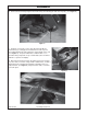
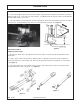
Figure 1
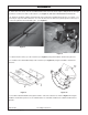
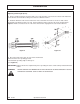
Figure 2
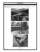
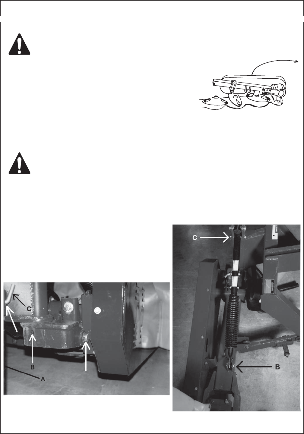
Figure 3
CAUTION!
CAUTION!
2. Attach the 3-point frame to the main frame as shown in illustration 2 using the mainframe pin and two roll
pins(B). Make sure the parts are clean and well lubricated.
3. Install the Stand Tube (A) in the 3-point frame and secure with the lock pin(C). (See Figure 2.)
4. Attach the suspension spring and suspension tube
assembly to the main frame and 3-point frame using a Short
Suspension Tube Pin (B) at the main frame and a Suspension
Rod Pin (C) at the 3-point frame. Secure both pins with cotter
pins. (See Figure 3.)
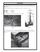
5. Install the Break Away Slide (D) into the rear clevis of the
3-point frame as shown in illustration 4. Secure with a pin and
cotter pin as shown.
BLOCKS SHOULD BE PLACED UNDER THE MAIN FRAME AND CUTTER BAR DURING
ASSEMBLY TO ADD STABILITY AND REDUCE THE CHANCE OF PERSONAL INJURY.
WEAR PROPER PROTECTIVE EQUIPMENT SUCH AS SAFETY GLASSES AND PROTECTIVE
SHOES WHEN ASSEMBLING THE MOWER. USE OVERHEAD CRANE OR HOIST.
See pages 6-1 through 6-22 in the Parts List Section and identify the
components to be installed. When the instructions refer to the left or
right side, they refer to your left or right side, as you are standing behind
the mower and facing the tractor. Refer to Torque Chart on Page 5-6 for
correct torque on all bolts.
The Rhino Disc Mower is shipped partially assembled. Refer to the parts
lists for the location of the parts.
1. Unpack the main frame and fold the frame away from the cutter bar. (See Figure 1.)