TURF FLEX Published 08/01 Effective Serial No. TX-10880 to Current P/N 00763618C OPERATOR'S MANUAL This Operator's Manual is an integral part of the safe operation of this machine and must be maintained with the unit at all times. READ, UNDERSTAND, and FOLLOW the Safety and Operation Instructions contained in this manual before operating the equipment. RHINO® 1020 S. Sangamon Ave. Gibson City, IL 60936 800-446-5158 Email: parts@servis-rhino.com © 2004 Alamo Group Inc. $0.
TO THE OWNER/OPERATOR/DEALER All implements with moving parts are potentially hazardous. There is no substitute for a cautious, safe-minded operator who recognizes the potential hazards and follows reasonable safety practices. The manufacturer has designed this implement to be used with all its safety equipment properly attached to minimize the chance of accidents. BEFORE YOU START!! Read the safety messages on the implement and shown in your manual.
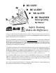
BE SAFE! BE ALERT! BE ALIVE! BE TRAINED before operating the Mower! Safety Training Makes the Difference In order to reduce accidents and enhance the safe operation of mowers, Alamo Group Ag Division, in cooperation with other industry manufacturers has developed the AEM/FEMA Industrial and Agricultural Mower Safety Practices video and guide book. The video will familiarize and instruct mower-tractor operators in safe practices when using industrial and agricultural mowing equipment.
Alamo Group Ag.
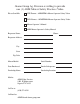
TABLE OF CONTENTS SAFETY SECTION ......................................................................................................................................... 1-1 Decal Location .............................................................................................................................................. 1-12 Decals ..........................................................................................................................................................
SAFETY SECTION Safety Section 1-1
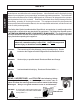
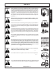
SAFETY SAFETY A safe and careful operator is the best operator. Safety is of primary importance to the manufacturer and should be to the owner/operator. Most accidents can be avoided by being aware of your equipment, your surroundings, and observing certain precautions. The first section of this manual includes a list of Safety Messages that, if followed, will help protect the operator and bystanders from injury or death.
SAFETY Never operate the Tractor or Implement until you have read and completely understand this Manual, the Tractor Operator’s Manual, and each of the Safety Messages found in the Manual or on the Tractor and Implement. Learn how to stop the tractor engine suddenly in an emergency. Never allow inexperienced or untrained personnel too operate the Tractor and Implement without supervision. Make sure the operator has fully read and understood the manuals prior to operation.
SAFETY Start tractor only when properly seated in the Tractor seat. Starting a tractor in gear can result in injury or death. Read the Tractor operators manual for proper starting instructions. (SG-13) DANGER! Never work under the Implement, the framework, or any lifted component unless the Implement is securely supported or blocked up to prevent sudden or inadvertent falling which could cause serious injury or even death. (SG-14) DANGER! Do not operate this Equipment with hydraulic oil leaking.
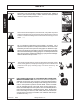
SAFETY Periodically inspect all moving parts for wear and replace when necessary with authorized service parts. Look for loose fasteners, worn or broken parts, and leaky or loose fittings. Make sure all pins have cotter pins and washers. Serious injury may occur from not maintaining this machine in good working order. (SG-21) WARNING! Never attempt to lubricate, adjust, or remove material from the Implement while it is in motion or while tractor engine is running.
SAFETY DANGER! Never run the tractor engine in a closed building or without adequate ventilation. The exhaust fumes can be hazardous to your health. SAFETY (SG-23) DANGER! KEEP AWAY FROM ROTATING ELEMENTS to prevent entanglement and possible serious injury or death. (SG-24) DANGER! Never allow children to play on or around Tractor or Implement. Children can slip or fall off the Equipment and be injured or killed. Children can cause the Implement to shift or fall crushing themselves or others.
SAFETY DANGER! WARNING! The rotating parts of this machine have been designed and tested for rugged use. However, the blades could fail upon impact with heavy, solid objects such as metal guard rails and concrete structures. Such impact could cause the broken objects to be thrown outward at very high velocities. To reduce the possibility of property damage, serious injury, or even death, never allow the cutting blades to contact such obstacles.
SAFETY SAFETY DANGER! Replace bent or broken blade with new blades. NEVER ATTEMPT TO STRAIGHTEN OR WELD ON BLADES SINCE THIS WILL LIKELY CRACK OR OTHERWISE DAMAGE THE BLADE WITH SUBSEQUENT FAILURE AND POSSIBLE SERIOUS INJURY FROM THROWN BLADES. (SGM-10) WARNING! Do not let the Blades turn when the Mower Deck is raised for any reason, including clearance or for turning.
SAFETY DANGER! Rotary Mowers are capable under adverse conditions of throwing objects for great distances (100 yards or more) and causing serious injury or death.
SAFETY SAFETY WARNING! Never leave Tractor and Implemented unattended while the implement is in the lifted position. Accidental operation of lifting lever or a hydraulic failure may cause sudden drop of unit with injury or death by crushing. To properly park the implement when disconnecting it from the tractor, lower the stand and put the retaining pin securely in place, or put a secure support under the A-Frame. Lower the implement carefully to the ground.
SAFETY PARTS INFORMATION SEE YOUR SERVIS-RHINO DEALER In addition to the design and configuration of this Implement, including Safety Signs and Safety Equipment, hazard control and accident prevention are dependent upon the awareness, concern, prudence, and proper training of personnel involved in the operation, transport, maintenance, and storage of the machine. Refer also to Safety Messages and operation instruction in each of the appropriate sections of the Tractor and Equipment Manuals.
SAFETY SAFETY NOTE: Rhino supplies safety decals on this product to promote safe operation. Damage to the decals may occur while in shipping, use, or reconditioning. Rhino cares about the safety of its customers, operators, and bystanders, and will replace the safety decals on this product in the field, free of charge (Some shipping and handling charges may apply). Contact your Rhino dealer to order replacement decals. 11' Models Attaches to Bolts on top of Divider Gearbox.
SAFETY NOTE: Rhino supplies safety decals on this product to promote safe operation. Damage to the decals may occur while in shipping, use, or reconditioning. Rhino cares about the safety of its customers, operators, and bystanders, and will replace the safety decals on this product in the field, free of charge (Some shipping and handling charges may apply). Contact your Rhino dealer to order replacement decals. 13-1/2', 14-1/2', 15-1/2', 16-1/2' Models 36 35 Attaches to Bolts on top of Divider Gearbox.
SAFETY SAFETY ITEM PART NO.
SAFETY 13 -- 02967827 Front Cover 15 -- 03200347 SMV reflector 16 -- 99203 Red Reflector 17 -- 99204 Yellow Reflector SAFETY 1 -- 00725746 3 -- 00756004 2 -- 00753840 5 -- 00756059 4 -- 00756005 Turf Flex 08/01 © 2004 Alamo Group Inc.
SAFETY SAFETY 14 -- D103 6 -- 00756494 18 -- 000678 9 -- 00763536 8 -- 00760657 11 -- 00769737 Turf Flex 08/01 © 2004 Alamo Group Inc.
SAFETY SAFETY 10 -- 00769736 19 -- 00755691 24 -- D302 25 -- 00763535 TURF FLEX Name 26 -- Model Number 27 -- Serial Plate 28 -- Serial Plate 29 -- Serial Plate 30 -- Serial Plate 20 -- 00763613 23 -- D301 Turf Flex 08/01 © 2004 Alamo Group Inc.
SAFETY SAFETY 22 -- D102 21 -- 00763977 8A -- 00773723 31 -00776481 Turf Flex 08/01 © 2004 Alamo Group Inc.
SAFETY FEDERAL LAWS AND REGULATIONS This section is intended to explain in broad terms the concept and effect of federal laws and regulations concerning employer and employee equipment operators. This section is not intended as a legal interpretation of the law and should not be considered as such. This Act Seeks: “...to assure so far as possible every working man and woman in the nation safe and healthful working conditions and to preserve our human resources...” DUTIES Sec.
INTRODUCTION SECTION Indroduction Section 2-1
INTRODUCTION This Rotary Mower is designed with care and built with quality materials by skilled workers. Proper assembly, maintenance, and operating practices, as described in this manual, will help the owner/operator get years of satisfactory service from the machine. INTRODUCTION The purpose of this manual is to familiarize, and instruct. The Assembly Section instructs the owner/ operator in the correct assembly of the Mower using standard and optional equipment.
INTRODUCTION INTRODUCTION Your Turf Flex is designed for light-duty cutting such as lawn maintenance plus small weed and grass control. With a reasonable amount of preventive maintenance, your Mower will provide years of dependable service. DANGER NEVER ALLOW CHILDREN TO OPERATE, RIDE ON, OR COME CLOSE TO MOWER OR TRACTOR.
INTRODUCTION ATTENTION OWNER/OPERATOR INTRODUCTION BEFORE OPERATING THIS MACHINE: 1. Carefully read the Operator’s Manual, completely understand the Safety Messages and instructions, and know how to operate correctly both the tractor and Mower. 2. Fill out the Warranty Card in full. Be sure to answer all questions, including the Serial Number of the Mower. Mail within 30 days of delivery date of this implement.
ASSEMBLY SECTION Assembly Section 3-1
ASSEMBLY DANGER! Operating with PTO speed over 540 RPM can cause excessive vibration with subsequent machine failure which can cause serious injury or even death. Never exceed 600 RPM. DEALER SET-UP INSTRUCTIONS Assembly of this mower is the reponsibility of the Rhino dealer. The mower should be delivered to the owner completely assembled, lubricated, and adjusted for normal cutting conditions. Set up mower as received from the factory with these instructions. Mower is shipped in bundles.
ASSEMBLY SWIVEL AND LIFT ARM ATTACHMENT Attach the Swivel Assembly on the Lift Arms using chrome plated Attaching Pin (1) retain with Roll Pin (2). Figure 3. Remove the Attaching Pin (3) from the Main Frame. Attach the Right and Left Lift Arm (Note Jack storage mount on Left Lift Arm only) to the Main Frame with attaching Pin (3). Secure with 1/2" x 1-1/2" bolt, (5) flatwasher, and locknut. Attach the Toggle Links (6) to the right and left Lift Arms with attachin Pin (4).
ASSEMBLY HYDRAULIC CYLINDER ATTACHMENT ASSEMBLY Attach the Rear Hydraulic Cylinder to the Main Frame with Fittings pointing down. Retain with Pin and Cotter Pin. Figure 5. Attach the Wing Hydraulic Cylinders to the the Main Frame and Toggel Links with Pins provided. Figure 6. FIGURE 5 FIGURE 6 WING MOWER ATTACHMENT NOTE: The Wing Mowers are right and left mowers.
ASSEMBLY CASTER WHEEL ATTACHMENTS REAR MOWER (FIGURE 8) Attach the right and left Axle Arm Weldment (1) to the deck with 3/8" Gr. 5 bolts (2) flatwasher (1-1/2OD x 3/16 thick) (3), and 3/8 locknuts (4). Install four one inch spacers (7) and two 1/4 inch spacer (8) on each fork and wheel assembly (9). Insert Wheel assembly Shaft (9) into Axle Arm Weldment (1) and retain with Snapper Pin (10). 1 10 10 3 8 8 7 7 5 6 6 1 7 9 5 4 3 3 2 6 7 9 2 4 3 FIGURE 8 NOTE bolt locations of stop.
ASSEMBLY ASSEMBLY CASTER WHEEL ATTACHMENTS WING MOWER (FIGURE 9) Attach the inside (1) and outside Axle Arm Weldments (1 or 1A) to the outer deck with 3/8" Gr. 2 bolt (2), flatwasher (1-1/2"OD x 3/16" thick) (3), and 3/8" locknut (4) installed in outer front hole. All other arm retaining bolts are Gr. 5, 3/8" bolts (5). See Fig. 13 & 14 for more details. Install spacer (7,8,9) and forks as describe in rear mower (Figure 8).
ASSEMBLY CASTER WHEEL ATTACHMENTS WING MOWER (11' MODEL) FIGURE 11 8 10 3 7 2 4 7 10 3 7 8 11 12 13 6 5 14 5 7 1 ASSEMBLY Attach the right and left Axle Arm Weldment (1) to the outer deck with 3/8" Gr. 2 bolts (2) flatwasher (1-1/ 2"OD x 3/16" thick) (3), and 3/8" locknuts (4) in the front hole in Arm. All other Arm retaining bolts are Gr. 5, 3/8" bolts. NOTE: Mount the inside and out side wing arms in the forward set of holes.
ASSEMBLY AXLE ARMS IN POSTION ASSEMBLY Note bolt locations of Axle Arms on 60" Deck. Figure 13. FIGURE 13 Turf Flex 08/01 © 2004 Alamo Group Inc.
ASSEMBLY AXLE ARMS IN POSTION Note bolt locations of Axle Arms on 72" Deck. Figure14 ASSEMBLY FIGURE 14 Turf Flex 08/01 © 2004 Alamo Group Inc.
ASSEMBLY DRIVESHAFT ATTACHMENT All drivelines are equipped with slide collars on end yokes. To attach to the shaft grab and pull the collar on the end of attaching yoke toward the opposite end of the driveline. Slide the yoke (with collar depressed) onto the shaft. Move the yoke back and forth until the collar clicks forward and locks yoke in place. Install the Jackshaft (1) on the Front Gearbox and install Bearing (2) on the Drive End. Sandwich the Bearing between the Bearing Supports(3) & (7).
ASSEMBLY WING DRIVESHAFT ATTACHMENT Standard Driveline Attach the wing driveline to the center power divider gearbox as shown so that both sides of the gearbox are oriented the same NOTE: The driveline end with the extended shield cone attaches to the mower deck gearbox. (FIGURE16) FIGURE16 Constant Velocity (CV) Driveline Attach the wing CV driveline to the center power divider gearbox with CV head at center box. Attach the end yokes so they are oriented in line the same as shown.
ASSEMBLY ROPE ROUTING FOR AUTOMATIC HEAD LOCKS ASSEMBLY Attach rope ends to latch at location shown in figure 18. FIGURE 18 NOTE: 11' Model Only Latch Angle Lift Arm Pin Ref. Hole wing arm Clearance Latch Latch Bolt Turf Flex 08/01 © 2004 Alamo Group Inc. Assembly Section 3-12 Adjust Latch Bolt to provide minimum clearance between Reference Hole and Latch. Over adjustment (too much clearance between Wing Arm and Latch) may cause inproper contact between Lift Arm Pin and Latch Angle.
ASSEMBLY NOTE: FIELD ASSEMBLY (FIGURE 19)- Head Locks 1. Loop ends back through welded link on lock bar and then inside of braid by forming a hole 16" from end. 2. Adjust lengths as shown to give 8" overlap and 4" loop. 3. Adjust to give diminsion shown. 4. Secure loops by running a plastic ties thru rope braids (2) to prevent slipping. NOTE: All lengths are before forming the loops. ASSEMBLY 11' Model Only NOTE: All lengths are before forming the loops.
.
OPERATION SECTION Operation Section 4-1
OPERATION The safe operation of this machine is the responsibility of the operator. The operator should be familiar with the mower and tractor and all safety practices before starting operation. This mower is designed for lawn or grass mowing. It is not designed for rough conditions or heavy weed mowing. It is equipped with suction type blades for best results in lawn mowing. Always operate tractor PTO at 540 rpm.
OPERATION NOTE: If attaching Mower Clevis, tractor drawbar must extend to rear to allow turning without binding in the Tongue Clevis. DO NOT USE THIS TYPE DRAWBAR WITHOUT STABILIZERS. Install washers the same as detailed previously. See art below.
OPERATION DRIVELINE ATTACHMENT TO TRACTOR 1. Grasp and pull collar on end of attaching yoke toward mower. 2. Slide yoke (with collar depressed) onto PTO shaft. 3. Move yoke back and forth until locking collar clicks forward and locks the yoke in place. WARNING! When attaching PTO yoke to tractor PTO shaft, it is important that spring activated locking collar slides freely and is seated in groove on PTO shaft. WARNING! Be sure PTO shielding and all other shielding is installed and is in good condition.
OPERATION STARTING & STOPPING MOWER Power for operating mower is supplied from tractor PTO. Refer to your tractor manual instructions for engaging and disengaging the PTO. Always engage the PTO at low engine rpm. Always operate at recommended PTO speed of 540 RPM. Learn how to stop tractor and mower quickly in case of an emergency. IMPORTANT: Stop mower and tractor immediately upon striking an obstruction. Inspect the mower and repair any damage before resuming operation.
OPERATION DETACHING AND STORING Lower the Mower to the Ground. Park the Tractor with the transmission in the correct gear ( Automatic Transmission-- Park; Standard Transmission--Neutral). Set the parking brake, shut off the engine, and remove the key. Wait until the PTO stops rotating before getting down from the tractor . Disconnect the driveline from the tractor PTO and store it to prevent it from contacting the ground. Always reinstall the master shield over the trator PTO Shaft.
OPERATION With the PTO NOT TURNING, slowly drive the tractor with mower attached through sharpest turn possible and watch shaft movement. With PTO NOT TURNING, slowly drive the tractor with mower attached through the most severe terrain conditions expected and watch Shaft movement. Check position which places driveline at maximum extended length and at maximum compressed length. Maximum extended length must always maintain at least 10 inches of profile tube engagement.
OPERATION If you have a condition where your tractor will be going up a steep incline with your mower still on the flat area or coming down the opposite incline, you have a potential problem. Figure 11. The correct preventive measure is to instruct the operator to cross this kind of terrain at an angle. Figure 10. This will reduce the angle between the tractor and the mower.
OPERATION CV DRIVELINE CHECK PROCEDURES The Main Driveline to tractor is equipped with a special constant velocity (CV) joint that allows the joint to run smooth with no vibration even at joint angles up to 80 degrees. This joint will operate and perform satisfactorily as long as it is not subjected to conditions which abuse it or go beyond its operating limits. 1. The constant velocity joint must be greased daily at 8 hour intervals. See Maintenance Section.
OPERATION TROUBLESHOOTING PROBLEM POSSIBLE CAUSE REMEDY STREAKING Slow Blade Speed Worn Blade Tips Operate PTO at 540 RPM. Replace with Genuine RHINO Blades. See your Rhino dealer. Sharpen blades uniformly. Slow ground speed of tractor but keep engine running at full PTO rpm. Cutting slower will help. Slow down until cured. Tighten per instructions. Apply belt dressing or replace with special RHINO belt. Tighten blade bolt securely. (Note: Left Hand threads Torque to 150 ft. lbs.
OPERATION TROUBLESHOOTING PROBLEM POSSIBLE CAUSE REMEDY BELT SLIPPAGE Mower overloading, material too tall or heavy Reduce tractor ground speed but maintain full PTO rpm. Cut material twice, one high pass and then mow at desired height. Cut a partial swath. Be careful not to over-lubricate. Clean lubricant from belt and pulleys with clean rag. Replace oil soaked belt. Check belt for free travel in pulleys and belt guides.
.
MAINTENANCE SECTION Maintenance Section 5-1
MAINTENANCE Before operating your Mower, make sure it is properly lubricated and thoroughy inspected. Only a minimum of time and effort is required to regularly lubricate and maintain this machine to provide long life and trouble free operation. WARNING! Always disengage the PTO before raising the mower for transporting or making adjustments. LUBRICATION INFORMATION Do not let excess grease collect on or around parts, particulary when operating in sandy areas.
MAINTENANCE GEARBOX The Gearboxes have been filled with lubricant to the Test Plug Level prior to shipment. However, you should check the oil level at Test Plug before operating, and frequently thereafter. The gearbox should not require additional lubricant unless the box is cracked or a seal is leaking. It is recommended that the oil level plug be removed after every 8 to 10 hours of operation and oil added until it runs out Test Plug hole. The Test Plug is located on the back of the Gearbox.
MAINTENANCE SWIVEL ASSEMBLY The Swivel Assembly should be lubricated every 8 hours. Figure 3. FIGURE 3 GAUGE WHEEL ASSEMBLIES MAINTENANCE Gauge wheels are equipped with bushings which require grease daily. Grease Fittings are provided in the Wheel Hub and Gauge Wheel Pivot . Grease after 8 hours of use. Figure 4 &5. FIGURE 4 FIGURE 5 BLADE SPINDLE LUBRICATION Blade spindles must be lubricated daily (every 8 hrs). Figure 6.
MAINTENANCE DRIVELINE LUBRICATION The Drivelines and U-Joints should be inspected each morning before the mower is started. FIGURE 7 The U-Joint and CV Joint on the Driveline undergo extreme forces when the unit is turning or when the Wings are being raised. It is important that the U-Joints and CV Joint be greased each day before the unit is started, and after each 8 hours of use. The U-Joints are located at each end of the Center and Wing Drivelines.
MAINTENANCE BLADE SERVICING Inspect blades before each use to determine that they are properly installed and in good condition. Replace any blade that is bent, excessively nicked, worn, or has any other damage. Small nicks can be ground out when sharpening. Use only original equipment blades on this mower. They are made of special heat-treated alloy steel. Substitute blades may not meet specification and may fail in a hazardous manner that could cause injury.
MAINTENANCE 4 2 3 1 5 FIGURE 10 3/4" 10 LBS. Flatwasher Locknut Flatwasher Bolt BELT ADJUSTMENT PROCEDURE (All Models except 11') Adjust the tension in the drive belt, item1, properly so that it deflects 3/4" when a force of approximately 10 lb. is applied as indicated. Tighten drive belt by loosening nut, items 2 & 5, and turn nut, item 3 against the anchor plate until proper tension is reached. DO NOT OVERTIGHTEN. Tighten jam nut, item 4., and nut item 2. And retighten item 5. FIGURE 10.
MAINTENANCE BELT ADJUSTMENT PROCEDURE (11' MODEL) Adjust the tension in the drive belt, item 1, properly so that they deflect 3/4" when a force of approximately 10 lb. is applied. Tighten drive belt by loosening one nut, items 2, and tightening other nut until belt is properly tensioned. Jam the first Nut to hold adjustment. NOTE: If more thread adjustment is needed loosen off and hook Spring (4) in next shorter Chain Link (3). Replace the belt safety shields using wing nuts.
MAINTENANCE STORAGE Your rotary mower represents an investment from which you should get the greatest possible benefit. Therefore, when the season is over, the cutter should be thoroughly checked and prepared for storage so that a minimum amount of work will be required to put it back into operation for the next season. The following are suggested storage procedures: 1. 2. 3. 4. 5. 6. Thoroughly clean the mower. Lubricate the mower as covered in Maintenance Section.
MAINTENANCE BLADE SPINDLE SERVICE INSTRUCTIONS (FIGURE 13) DISASSEMBLY 1. Remove adjusting nut #3. 2. Support spindle housing #2 under flange and drive out shaft assembly #1. CAUTION! Use tube on top end of shaft to protect grease fitting. 3. Remove bearing cups from housing. Remove lower bearing from shaft assembly by inserting punch through hole in shaft hub and drive bearing off shaft. Once bearing has been moved 3/8" - 1/2" up shaft, lay flat bars on either side of the shaft and support across vice..
MAINTENANCE CLUTCH ASSEMBLY (Figure 14) 1. Remove snap ring (1). This allows removal of complete quick coupler (13,14,15,2) and three locking clutch balls (18). 2. Tighten four hex nuts (10) until spring assembly (9 and 12) are loose in main housing (3). NOTE: Small amount of lubricant on nut and threaded stud will avoid problem of twisting studs off. 3. Place clutch in vise so it can be held firm during next step. 4.
TO THE OWNER/OPERATOR/DEALER To keep your implement running efficiently and safely, read your manual thoroughly and follow these directions and the Safety Messages in this Manual. The Table of Contents clearly identifies each section where you can easily find the information you need. The OCCUPATIONAL SAFETY AND HEALTH ACT (1928.51 Subpart C) makes these minimum safety requirements of tractor operators: REQUIRED OF THE OWNER: 1. 2. 3. 4.
TURFFLEX-OMWPL-08/01 Printed U.S.A.