
Lawn Mower User Manual


Assembly Section 3-3
ASSEMBLY
© 2004 Alamo Group Inc.
ASSEMBLY
Turf Flex 08/01
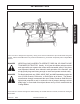
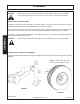
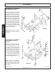
SWIVEL AND LIFT ARM ATTACHMENT
Attach the Swivel Assembly on the Lift Arms using chrome plated Attaching Pin (1) retain with Roll Pin (2). Figure
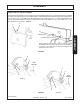
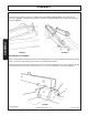
3. Remove the Attaching Pin (3) from the Main Frame. Attach the Right and Left Lift Arm (Note Jack storage mount
on Left Lift Arm only) to the Main Frame with attaching Pin (3). Secure with 1/2" x 1-1/2" bolt, (5) flatwasher, and
locknut. Attach the Toggle Links (6) to the right and left Lift Arms with attachin Pin (4). Secure with 1/2" x 1-1/2"
bolt, flatwasher, and locknuts. Figure 4.
1
2
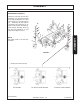
NOTE: If Mower is a 14-1/2 ft. or 16-1/2 ft. unit, the Swivel
is installed in the outer hole of the Lift Arm. If the Mower is
a 13-1/2 ft. or 15-1/2 ft. unit, the Swivel is installed on the
inside hole of the Lift Arm.
INSIDE HOLE
OUTER HOLE
FIGURE3
R 11-20-95
Jack
Storage
Jack
Storage
3
5
FIGURE4
3
4
6
5
6
4
left wing
right wing