
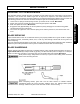
Operator`s manual


MAINTENANCE
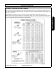
TX165A,135A,115A 02/11 Maintenance Section 5-14
© 2011 Alamo Group Inc.
MAINTENANCE
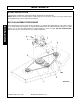
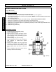
BLADE SPINDLE INSTRUCTIONS
(Figure Mnt-R-0195)
ASSEMBLY PROCEDURE
1. Press (Item 6) Cup into both ends of (Item 3) Housing Spindle.
2. Install (Item 5) Bearing into (Item 6) Cup on bottom side of (Item 3) Housing Spindle.
3. Press (Item7) Seal into bottom of (Item3) Housing Spindle. (NOTE: POSITION & DIRECTION OF SEAL
FLUSH WITH HOUSING)
4. After Completing Steps 1-3
5. Press Housing/Bearing Assembly. Onto Shaft Assembly. DO NOT USE HYDRAULIC PRESS
6. Drive (Item 5) Top Bearing onto (Items 1&2) assembly. shaft seal protector.
7. Press (Item 7) seal into top of (Item 3) housing spindle. (Note position & direction of seal)
8. Install (Item 4) nut adjusting (Adjust nut to give bearing end play of 0.002"-0.006" apply loctite 242 to nut.)
9. Install (Item 9) set screw
10. Install (Item 10) grease fitting.
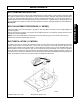
Disassembly Procedure
1. Loosen set screw (9) in adjusting nut (4).
2. Remove adjusting nut (4)
3. Support housing (3) flange and press or drive
shaft assembly (1) from housing, taking care to
prevent damage to the grease fitting (10) and
shaft (1) threads.
4. Remove bearing cups (6) from housing.
5. Reinstall adjusting nut (4) on shaft and support
shaft assembly (1) upside down against
adjusting nut
6. Remove lower bearing cone (5) from shaft
assembly by inserting a 3/16" diameter drift
punch through holes in seal protector (2) and
driving bearing down until loose on the shaft
(1).
7. Remove adjusting nut(4) and continue driving
bearing off the rest of the shaft (1).