CVG Installation Guide May 2012
SerVision CVG Installation Guide Trademarks & Copyright Trademarks All trademarks mentioned in this manual are the sole property of their respective manufacturers. Copyright SerVision Ltd., Jerusalem, Israel www.servision.net • info@servision.net © 2012 SerVision Ltd. All rights reserved. Notice Information in this document is subject to change without notice. SerVision Ltd. assumes no responsibility for any errors that may appear in this manual.
SerVision CVG Installation Guide Table of Contents Introduction 3 The CVG Package 4 Additional Equipment 5 Installing the CVG System 6 Selecting a Location for the Unit 6 Diagrams of Connectors 6 Supplying Power to Devices Connected to the Unit 8 Connecting Devices to the CVG Connecting Cameras Connecting a PTZ Controller Connecting Sensors Connecting a Sensor Directly to the Unit Connecting Sensors Using an ADAM Module 9 9 9 11 11 12 Connecting Activators 15 Connecting Sensors and Activ
SerVision CVG Installation Guide Introduction This guide explains how to set up the hardware components of SerVision’s standard CVG security system. The standard CVG belongs to SerVision’s line of embedded Video Gateway units. These units provide state-of-the-art security functionality, including live video streaming, video recording and playback, motion detection, sensor management, real-time event notification, and device activation.
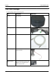
SerVision CVG Installation Guide The CVG Package The CVG package contains the following items: Item Description CVG unit Video gateway Power supply cable Connects the unit to an electrical outlet Ethernet (LAN) cable Connects the unit to a local network RS232/485 adapter Connects PTZ controllers or other devices to the unit Micro SD memory card Stores recorded video and other data The CVG Package Illustration Note: The unit is supplied with the memory card in its slot.
SerVision CVG Installation Guide Additional Equipment One or two video cameras should be connected to the CVG. You must acquire the cameras you require; they are not included in the CVG package. For information about camera compatibility and about connecting the cameras to the unit, see Connecting Cameras, page 9, or consult your vendor. In addition to the cameras, you may wish to connect some or all of the optional equipment listed below to the CVG unit.
SerVision CVG Installation Guide Installing the CVG System These are the steps that you will typically follow in order to install the CVG system: 1. Place the CVG unit in its desired location; see Selecting a Location for the Unit, page 6. 2. Install the video cameras in their desired locations. 3. Install a CCTV monitor in its desired location (optional). 4.
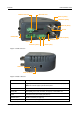
SerVision CVG Installation Guide Micro SD Card 12VDC Power Out Audio In (Ain1) Audio Out (Aout) Video In (Vin2) TV-Out RS232/485 Video In (Vin1) Ethernet Out Power Activator (Out1) Sensor (In1) Figure 1: CVG connectors Audio Out Audio In (Ain1) Figure 2: Audio connectors Connector Description 12VDC Power Out Supplies power to external devices, such as cameras and sensors (see page 8) Note: The unit can supply up to 250 mA of power.
SerVision CVG Installation Guide Connector Description Ethernet Out 10/100 Base-T LAN connector for connecting the unit to an external network (LAN or WAN; see page 21) TV Out Connector for a CCTV monitor (see page 18) Video In (Vin1 and Vin2) Connectors for video cameras (see page 9) Audio Out (Aout) Connector for an external speaker or headphones (see page 18) Audio In (Ain1) Connector for a microphone (see page 17) Supplying Power to Devices Connected to the Unit The CVG can supply power di
SerVision CVG Installation Guide Connecting Devices to the CVG This section explains how to connect devices such as a camera or a sensor to the CVG unit. Connecting Cameras Up to two cameras can be connected to the CVG. If the cameras have PTZ controls for remote aiming and zooming, and the PTZ protocol they use is supported, the control cables can also be connected to the unit. Any PAL or NTSC video camera with a composite video output can be connected to the unit.
SerVision CVG Installation Guide If you connect two RS485 PTZ camera controllers, they should be daisy-chained to the RS232/485 connector, as described below. In this case, each camera in the chain must be given a different ID number. Please refer to your camera's documentation for information about configuring its ID number. In addition, note that you can only create an RS485 daisy chain if both cameras use the same PTZ protocol.
SerVision CVG Installation Guide Connecting Sensors Sensors are devices that detect events such as a door being opened or a light being turned on. A dry-contact input sensor can be connected directly to the unit. Alternatively, the sensor connector on the unit can be used to connect a switch to change the active outline or the display on a connected CCTV monitor. In addition, if you wish, you can connect either an ADAM Data Acquisition Module or an IA-3126-2 relay board to the unit.
SerVision CVG Installation Guide Connecting Sensors Using an ADAM Module If you want to connect additional dry sensors to the CVG, you can do so by connecting an ADAM Data Acquisition Module to the unit. Up to 16 additional dry sensors can then be connected to the unit through the ADAM module. NOTE: Alternatively, you can connect additional sensors using an IA-3126-2 relay board, as explained Connecting Sensors and Activators Using an IA Relay Board, page 16.
SerVision CVG Installation Guide D GND D1 0 through D1 10 Connect sensor ground wires to this connector Connect positive (+) sensor wires to these connectors D GND D1 11 through D1 15 Connect sensor ground wires to this connector Connect positive (+) sensor wires to these connectors Figure 9: Connecting sensors to the ADAM-4051 module 3.
SerVision CVG Installation Guide Plug into RS232/485 connector on MVG RS232 connector Figure 10: RS232/485 adapter Note: If you connect an ADAM module to the unit, you cannot connect any RS232 PTZ controllers, a touchscreen controller, or an IA relay board to the unit. For additional information, see Connecting a PTZ Controller, page 9; Connecting a CCTV Monitor, page 18; Connecting Sensors and Activators Using an IA Relay Board, page 16. 5.
SerVision CVG Installation Guide Note: You may be able to use the CVG to supply power to the modules by connecting the power supply cables to the 12VDC Power Out connector on the rear panel of the unit. However, bear in mind that the unit can supply a maximum of 250 mA (3W) of power. If the devices connected to the unit require more than this amount of power, you must power some or all of them independently (see Supplying Power to Devices Connected to the Unit, page 8).
SerVision CVG Installation Guide Activator + Power - CVG rear panel Input/Output terminal block Out1 In1 Figure 12: Connecting an activator that has its own power supply Connecting Sensors and Activators Using an IA Relay Board If you want to connect additional dry sensors and/or one activator to the CVG, you can do so by connecting an Intelligent Appliance IA 3126-2 relay board to the unit.
SerVision CVG Installation Guide NOTE: If you are connecting less than 16 activators or 16 sensors to the relay board, be sure to connect them to the relay beginning with the lowest connector, and do not leave open connectors between those that you use. For example, if you are connecting 4 activators and 3 sensors, connect the activators to output connectors 1-4 on the board and the sensors to input connectors 1-3 on the board. To connect the IA 3126-2 relay board to the CVG: 1.
SerVision CVG Installation Guide Connecting a Speaker or Headphones The CVG unit contains a built-in, 1-watt, internal speaker, which is located on top of the unit. You can also connect an external speaker or headphones to the unit. The speakers (and headphones) allow you to hear audio that is transmitted from client applications. The external speaker or headphones can be used in addition to the internal speaker or instead of it.
SerVision CVG Installation Guide An appropriate connector (BNC or RCA) for the Video In connector of the monitor. (Consult the monitor documentation or your vendor to find out which kind of connector is required for the particular monitor you are using.) A BNC male connector to connect to the TV Out connector of the CVG. (A cable with an RCA connector can be used by attaching a BNC-to-RCA adaptor to the connector. See figure 7, page 9.
SerVision CVG Installation Guide Connecting Multiple Monitors If you wish, you can connect multiple CCTV monitors to the CVG. For example, you may wish to have one monitor beside the driver’s seat and another beside the conductor’s seat. To connect multiple monitors, you must use video splitters to split the connection. Bear in mind, however, that the image quality in each of the monitors will be slightly degraded. To correct this problem, you can use a video amplifier (booster) for each monitor.
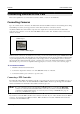
SerVision CVG Installation Guide Connecting the CVG to a Network The standard CVG should be connected to a local network using a network cable. Once connected, it can be accessed either from a PC on the same LAN network or via the internet through the LAN’s gateway (router). To connect the CVG unit to a LAN: Connect the Ethernet Out connector on the CVG unit to a LAN connection point (a hub, wall socket, or any other connection point) using the supplied Ethernet cable (see The CVG Package, page 4).
SerVision CVG Installation Guide Connecting the CVG to a Power Source The standard CVG must be connected to an electrical outlet using the supplied power-supply cable. Once it is connected, the unit starts up automatically. During the start-up process, the Power LED on the top of the unit flashes at various intervals. When the start-up process is completed successfully, the Power LED should display as a solid color and blink momentarily every second.
SerVision CVG Installation Guide Appendix: Removing the Micro SD Card The CVG unit stores all recorded video and event information on a standard micro SD card. The unit is supplied with a 4 GB micro SD card. You can remove this card from the unit in order to copy video files from it and/or replace it with a different micro SD card. NOTE: The CVG cannot record video or event information unless an appropriate micro SD card is in the card slot.
SerVision CVG Installation Guide To insert a micro SD card into the unit: Hold the card as illustrated below and push it gently into the card slot until it clicks into place. Hold the card on this edge, with the lettering facing up.
POB 45205 Jerusalem 91450 Israel Tel: +972-2-535 0000 • Fax: +972-2-586 8683 www.servision.net • info@servision.