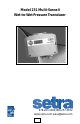
Model 231 Multi-Sense® Wet-to-Wet Pressure Transducer 978-263-1400; 800-257-3872 www.setra.com; sales@setra.
Contents 1.0 GENERAL INFORMATION ...................................................................... 4 2.0 MECHANICAL INSTALLATION ............................................................. 4 2.1 Media compatibility........................................................................ 4 2.2 Environment ...................................................................................... 4 2.3 Pressure Fittings ............................................................................... 5 2.
Model 231 Installation Guide Multi-Sense® Model 231 Series Wet-to-Wet Differential Pressure Transducers 1.0 GENERAL INFORMATION Every Model 231 has been calibrated and tested before shipment to guarantee performance of all pressure ranges. The Model 231 has field selectable unidirectional and bidirectional pressure ranges, configurable 0 to 5 VDC, 0 to 10 VDC , and 1 to 5 VDC output, true two-wire 4 to 20 mA output, and auto-zero capability. The Model 231 is factory calibrated to the highest pressure range.
2.3 Pressure Fittings Typically standard pipe fittings and installation procedures should be used. The Model 231 has 1/8” −NPTF internal fittings. The high pressure port and low pressure port are located on the bottom of the unit , labeled “HI” and “LO”, respectively. The optional 3-valve manifold assembly is supplied with 1/4”–18 NPT internal fittings. Moisture Precautions The Model 231 is provided with a 0.875 DIA. conduit opening for electrical termination, intended for a 1/2” I.D. conduit connection.
Model 231 Differential Pressure Transducer V3 Shunt Valve 3-Valve Manifold Description Manifold Block Valves (3) Shut Off Valves V1 High Process Connection 1/8-NPT Valve Type Process Connections V2 Brass V1 for connection to + port V2 for connection to - port V3 for equalizing pressure 90 degree On/Off 1/4-18NPT Internal Thread Low Process Connection 1/8-NPT Figure 2 3.0 OPTIONAL 3-VALVE MANIFOLD PROCEDURE The 3-Valve Manifold Assembly is normally shipped with valves V1 and V2 closed and V3 open.
Model 231 - Outline Drawing 6.0 152 5.6 141 R 0.1 2 0.3 9 2.0 51 1.2 31 1.7 42 2.0 51 Front View 4.0 102 4.6 117 4.8 122 5.2 131 Side View 1.6 40 1/8” NPTF 1.0 24 Bottom View 1/2” Conduit Opening Figure 3 7 in.
4.0 ELECTRICAL INSTALLATION To access the electrical connections, turn the screws on the top of the case counter clockwise until the hinged cover can be flipped up. The screws are captured and secured in the cover. Wiring is through the 1/2” conduit opening. Both current and voltage outputs are reverse wiring protected. Note: The Zero terminals, connected to digital output, provide a contact closure relay for automatic reset to zero pressure by the monitoring system.
4.2 Electrical Termination Wiring: 3-Wire, 0 to 5, 0 to 10, 1-5 VDC and Remote Zero The Model 231 when configured for voltage output is a 3-wire circuit device with three terminals available for wiring. The -Excitation and -Output are commoned on the circuit. The 231 can operate from 12-30 VDC (18-28 VAC) nominal output power supply. Note: The Zero terminals, connected to digital output, provide a contact closure relay for automatic reset to zero pressure by the monitoring system.
5.0 OPERATION Auto Zero Button Range Selection Switch A B C D EXC. B 25 50 125 A B C D ZERO RANGES A MS1 50 MS2 100 MS3 250 + + - Electrical Output C D 10 5 20 10 50 25 OUTPUT A B C D 4-20 0-5 0-10 1-5 Configurator BAR A.REV SLOW BI-DIR SWAP PSI NORM FAST UNI-DIR NORM OUT COM + 4-20 MA REMOTE ZERO Electrical Connections Figure 6 Range Selection Switch: The unit is set to the highest range when calibrated at the factory. To select the other ranges, slide the switch to the right.
6.0 RETURNING PRODUCTS FOR REPAIR Please contact a Setra application engineer (800-257-3872, 978-263-1400) before returning unit for repair to review information relative to your application. Many times only minor field adjustments may be necessary. When returning a product to Setra, the material should be carefully packaged, and shipped to : Setra Systems, Inc.
RoHS 159, Swanson Road, Boxborough, MA 01719 978-263-1400; 800-257-3872/www.setra.com; sales@setra.