MODEL 760 VACTRON SERIES OPERATING INSTRUCTIONS ISO 9001 ✓ Certified 1-800-257-3872 TOLL FREE 1-978-264-0292 FAX sales@setra.com EMAIL www.setra.
Setra offers a complete line of products for the semiconductor industry.
Contents 1.0 Introduction ............................................................................................. 1 2.0 Mechanical Installation ........................................................................ 2 3.0 Electrical Installation .............................................................................. 5 4.0 Operation ................................................................................................... 7 5.0 Calibration and Adjustment of Zero Output ................
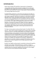
1.0 Introduction Setra's Vactron Model 760 capacitance manometer is a temperature compensated, absolute pressure transducer designed for accurate and repeatable vacuum measurements. Various full scale ranges are available from 10 Torr up to 1000 Torr. The units of measurement may be specified in Torr (mmHg), mBar (hPa), kPa or psia. The Model 760 operates from a ±15 V DC power supply and provides a 010 V DC or 0-5 V DC signal output that is linear with pressure and independent of gas composition.
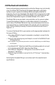
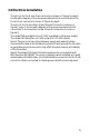
2.0 Mechanical Installation Remove all packaging material and the protective flange cover and visually check the Model 760. If the Model 760 appears damaged, notify Setra Systems or your supplier immediately. Retain packaging materials for inspection. Do not use if damaged. If the Model 760 is not going to be used immediately, then replace the protective flange cover and store in an area where the temperature range is controlled between -50 to +125°C.
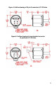
Figure 1: Outline drawing of 15 pin D connector, 0.5" OD tube. Figure 2: Outline drawing of screw terminal connector (6 position), 0.5" OD tube.
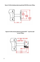
Figure 3: Outline drawing showing optional ISO NW vacuum fitting. Figure 4: Outline drawing showing optional VCR™ style face seal vacuum fitting.
3.0 Electrical Installation The pin out for the D-sub, 15 pin connector is shown in Figures 5, page 6. A schematic diagram of the recommended electrical connections to the D-sub, 15 pin connector is shown in Figure 6, page 6. The pin out for the 6-Position Screw Terminal Connector is shown in Figure 7, page 7. A schematic diagram of the recommended electrical connection to the 6-position Screw Terminal Connection is shown in Figure 8. The model 760 operates from a ±15 VDC regulated (±5%) power supply.
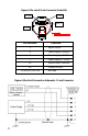
Figure 5: Pin out of D-sub Connector (Code D2) Pin 15 Pin 9 Pin 1 Pin 8 Pin Location Function 2 Signal Output 5 Power Supply Common 6 Power Supply, -15 VDC 7 Power Supply, + 15 VDC 12 Signal Output Common 15 Chassis Ground 1,3,4,8,9,10,11,13,14 Not used Figure 6: Electrical Connection Schematic - D-sub Connector 6
Figure 5: Pin out of D-sub Connector (Code D2) Pin 15 Figure 7 : Pin out of Screw Terminal Connector (Code T2): Pin 9 Pin 1 Pin 1 Pin 8 Pin Location Function Pin Location Function 2 Signal Output 1 Power Supply Common 5 Power Supply Common 2 Signal Output Common 6 Power Supply, -15 VDC 3 Signal Output 7 Power Supply, + 15 VDC 4 Power Supply, -15 VDC 12 Signal Output Common 5 Power Supply, + 15 VDC 15 Chassis Ground 6 Chassis Ground 1,3,4,8,9,10,11,13,14 Not used Figure 8 :
4.0 OPERATION For most accurate pressure measurement, allow the Model 760 to warm up for at least 15 minutes. After installation, periodically check the zero output reading to verify correct output. Adjust the zero potentiometer if incorrect (See Section 5 for zero adjustment instructions). The signal output of the Model 760 is linear with pressure; e.g., for a 10 VDC FS Model 760, 10 VDC equals 100% FS output, 1 VDC equals 10% FS output.
5.0 Calibration & Adjustment 5. 1 Checking & Zero Adjustment After installation on a system, the Model 760 may require initial zero adjustment. Figure 9 shows the location of the zero adjustment potentiometer. Slide open the black plastic insert to reveal two access holes. The access hole next to the raised "Z" on the plastic cover identifies the Zero potentiometer. Use an accurate digital voltmeter to view the signal output of the Model 760. Adjust the signal output of the model 760 to be 0.001 to –0.
6.0 Maintenance & Troubleshooting There are no general maintenance requirements for the Model 760 other than periodic zero adjustment. If the unit fails to operate when received or if the unit appears damaged, notify Setra Systems or your supplier immediately. Retain packaging materials for inspection. Do not use if damaged. If the Model 760 is not going to be used immediately then replace the protective flange cover and store in suitable conditions described in Section 2.
7.0 Specifications Performance Data: Accuracy (RSS)1 : < ± 0.25% of Reading Optional < ± 0.15% of Reading 0.01% FS Resolution: Thermal effects Compensated Range: Zero Shift: Span Shift: Proof Pressure: Operating Temperature: Storage Temperature: 0 to +50°C < ± 0.005% FS / °C < ± 0.
8.0 Reordering Data Example: To order a 10 Torr FS unit with ISO NW16 fitting, 0-10 VDC output, D sub 15 electrical connector and an accuracy of ±0.25% Reading, the order code would be: 7601010TAN17CD2A. 9.0 Returning the Model 760 for Repair Setra Systems cannot accept a Model 760 for repair unless the Form 760ERN is completed. Contact Setra Systems for an ERN Number or the Form 760ERN. Form 760ERN is included in this guide on page 15.
diagrams. Allow approximately 3 weeks after receipt at Setra for the repair and return of the unit. Non-warranty repairs will not be made without customer approval and a purchase order to cover repair charges. Calibration Services Setra maintains a complete calibration facility that is traceable to the National Institute of Standards & Technology (NIST).
11.0 RETURN OF SETRA SYSTEMS PRODUCT-DECLARATION (Form 760ERN) EXPECTED RETURN NUMBER _____________________________________________ You must: • Know about all of the substances which have been used and produced in the product before you complete this Declaration. • Contact your supplier if you have any questions and for an ERN Number. • Send this form to your supplier with the return of the product. SECTION 1: Product A. Model Number ________________________ B. Serial Number ________________________ C.
SS2037 Rev.E 02/06/01 MODEL 760 VACTRON SERIES OPERATING INSTRUCTIONS 159 Swanson Road, Boxborough, MA 01719-1304 Tel: 800-257-3872/978-263-1400, Fax 978-264-0292 Email: sales@setra.com, Web: www.setra.com ISO 9001 ✓ Certified 1-800-257-3872 TOLL FREE 1-978-264-0292 FAX sales@setra.com EMAIL www.setra.