Model SRCM Operation 1
Contents OPERATION......................................................................................................................................................................... 4 Condition Banner ................................................................................................................................................... 6 Condition Banner – Touch Screen ......................................................................................................................
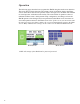
Operation The following pages describe how to operate the SRCM using the touch-screen interface. The screen has two basic functions. The primary mode of operation displays the Home screen, which shows the end-user pressure values, messages, text, and other data intended for visual pressure verification in the facility. The second mode of operation is the Administrative Menu screen, which permits setup, configuration, and changes to how the SRCM operates.
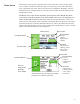
Home Screen The default screen now has 2 possible modes. Now if the user wants to display other room variables in addition to Pressure they can switch to the screen below that shows up to 4 parameters per room. These can be Pressure, Temperature, Humidity, and userdefined. The User switches modes by selecting slider on/slider off on the bottom of the administrative menu. The Home screen is the normal continuous operating mode of the SRCM.
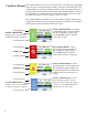
Condition Banner The Condition Banner is the left 1/3rd portion of the screen that can be configured by the end-user or facility manager to display a message to staff on the floor. The Condition Banner can be Green, Yellow, or Red or Blue, depending on the type of message desired outside the pressurized space. The Condition Banner is set up in the Setup Display-Condition Banner tab of the Administrative menu.The Condition Banner also has an option to display in full screen mode.
Condition Banner – Touch Screen Operation Once the messages of each of the four Condition Banners are defined in the Menu section, the user can cycle through all four conditions by simply touching the left onethird of the screen in any region. If passwords are enabled, the user will be prompted to enter their password before proceeding. Each of the four colored screens can have a unique message defined. See Section: Setup Display, page 11, for instructions on how to setup the Condition Banner.
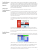
Operating Condition Screen The Operating Condition screen shows the user the active operating conditions of the pressurized space. Room Label Pressure Mode Pressure Value Slider Bar and Alarm Setpoint Values • Positive • Negative • Neutral (span) • Standby Operation • Normal (green) • Warning (yellow) • Door (yellow) • Alarm (red) The Room Label at the top of the screen can be defined by the user to ensure the viewer understands which room is actively being monitored by the SRCM.
A black banner displays the actual pressure reading from the space, in either Water Column inches (“ WC) or Pascals (Pa). The resolution of display can vary, depending on desired configuration; either 2, 3, or 4 significant digits. The accuracy of measurement remains the same regardless of the number of digits chosen. Pressure Value Slider Bar and Set Point Values The blue banner below the pressure value shows where the current pressure reading is in relation to alarm setpoints.
Active and Standby Modes By pressing the touch-screen directly on the word POSITIVE (or NEGATIVE, NEUTRAL, or STANDBY), the user is able to change the condition of the room between ACTIVE and STANDBY modes. A pop-up menu appears to enable selection. If passwords are enabled, the user must first enter a password to proceed with the change. In ACTIVE mode, the full function of the SRCM is active.
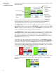
Menu Screens Pressing the MENU button on the Home screen brings up the Administrative Menu. If passwords are enabled, the user is required to enter the correct password before being authorized to make changes. From the Administrative Menu, the user can set all operating parameters of the SRCM. This includes initial setup, commissioning, calibration, Network setup, customizing the displays, and warning and alarm parameters.
parameters specific to the job site. Setup Unit The SRCM can take as input, the signal from two separate pressure transducers as well as temperature, humidity, and user defined (ex. CO2) inputs for up to two rooms. These are configured for either Primary Room or Secondary Room (an anteroom is an example of a secondary room).
Room Parameters The SRCM can display up to four (4) parameters for each of 2 rooms. The parameters can be Pressure, Temperature, Humidity, and the fourth user defined (Ex., CO2). Start with the Primary Room and set up the Parameters to be monitored and displayed on the default or home screen. As Parameters and inputs are selected further selection of parameters and inputs will become self limiting (Ex., If Temperature is selected in Parameter 2, it is not available for selection in Parameter 3 or 4.
Analog Inputs The SRCM has 2 Analog Input Channels (ADC-CH1 and ADC-CH2) Note: If a 4-20 mA transmitter is used as an analog input then a 250 ohm resistor must be field installed and this will be translated into a 1-5 VDC input at the input terminals. This takes an analog input from any transducer or transmitter: pressure, temperature or humidity.
tive humidity. The range is 0-98 %RH with a 0-10 VDC output. Changing Room Name The room name shown on the top part of the Home screen is changed using the Room Label button. The Room Name entry box appears in the middle of the Setup Unit display. Depending on whether the Primary or Secondary ROOM radio button is enabled, the matching Room Name entry box appears. The maximum number of characters is 18.
Setup Display to configure Condition Banner messages and other Home screen options. There are four tabs for display customization; General, Advanced, Condition Banner, Set Time and Date. The General tab allows the user to define messages for each Condition Banner General Tab — Custom- color. Pressing anywhere in the colored region of the Condition Banner changes each selection between GREEN, YELLOW, RED, and BLUE.
displayed on the Operating Condition section of the Home screen. The display Advanced Tab– contrast level is adjusted using Adjust Contrast Level, with selections from Customizing the Operation 1-4. After modifying this parameter, press Save & Exit to view the brightness and contrast on the Home screen display. Depending on the lighting and viewCondition Screen ing conditions in the final space, different contrast levels can improve readability of the SRCM.
If this is set to Secondary Only, then the Home screen will show the pressure value read by the secondary pressure transducer (anteroom for example). In this case, if an alarm condition occurs in the primary room, the display will toggle and remain on the primary room and pressure value as long as the alarm condition is present in that space. If no Secondary Room is configured on the Setup Unit screen, attempts to choose Secondary Only will result in the error “Secondary room source is NONE.
Condition Banner Tab- The Condition Banner can be used for control function as well as pure communiCustomizing Blinking cation. There are three choices for each color: Active, Standby, and No Action. Screens Used for setting actions that is associated with each banner color These apply to the right side of the Home Screen The Condition Banner tab allows the user to choose whether certain parts of the screen blink or not.
Full Screen Condition Banner and Active Standby Mode Application Customers may want a minimal user interface and want to switch between Active and Standby Modes and clearly convey the status of the room. Note: Any color can be associated with any action: Active, Standby, or No Action. The following example uses GREEN for Active and YELLOW for Standby. 1. On the setup Display/General tab set User defined Text to Enabled. 2. Tap the condition banner screen until the green screen is displayed.
5. With this setup the unit is in Active Mode. The Full Screen Display will look like the following with the text that was specified in step 2: 6. If the User changes the Standby by touching the section to the right of the PRESSURE, then the display will show up in yellow with the text that was specified in step 3. 7.
Set Time & Date Screen The Set Time & Date tab is used for setting the time and date of the SRCM. This time and date is used to time stamp the event log. See Event Log Section. Note: If power is lost to the unit, the time, and date need to be reset. If BACnet is used and is connected to the network, the time and date will automatically be retrieved. The date format is DD-MM-YYYY.
Audible Alarm Mute Time Out Digital Input (DI) Deadband Buzzer Volume Enables or disables the audible buzzer. Regardless of whether audible alarming is enabled or disabled, the red ALARM condition will show on the Home screen, annunciate to an SRAN, and propagate to a configured Digital Output. If an alarm occurs and the audible alarm is enabled, a new SILENCE button will appear on the Home screen so that the operator can silence the audible alarm.
Alarms Disabled when Door The SRCM is able to configure the Room status to disable the Alarms when Door is open. This function is used when there will be high traffic through Open & Buzzer for Door the area and the user wants to disable any alarms that are occurring as the Warning result of the door being open. The alarms will be re-enabled once the Door is closed. In the Alarm Setup screen, select the digital input choice to Door Alarm.
Alarm Set Point For each space, Primary Room or Secondary Room, this screen is used to define the alarm setpoints. When the room is then set to Positive, Neutral, or Negative, the setpoints and conditions configured here are in effect for alarm and warning conditions. Alarm Matrix The SRCM has a great deal of flexibility to define alarm conditions. Alarms and warnings can be configured for primary and secondary rooms, and for the door. Room display can toggle between Primary and Secondary.
Toggle Disabled Disabled Disabled Enabled Enabled Enabled Enabled Enabled Enabled Enabled 26 High Priority Display Background Remarks Text (MaxiPrimary Secondary Pressure Pressure mum eight characters) A N Alarm Red Shows Alarm for secondary room if secondary room is selected for display. If the pressure to display is selected as Primary, display switches to the secondary room to show the alarm. A A Alarm Red Display toggles between primary and secondary room.
Calibration and Self-Test This page is used for calibration of the internal pressure transducer sensor and testing operation of hardware circuitry. Calibration is only required for highly accurate measurement needs such as those needed to comply with federally mandated regulations. Calibration should only be performed by qualified personnel. 1. Select Primary or Secondary room.
Zero Adjust Span Adjust Restore Factory User Zero and User Span Test System Information This requires the use of a Pressure Calibrator, such as a Setra Model 869 or equivalent. Connect tubing from the Calibrator to the low and high ports identified near the PCBA markings. Apply Full Range pressure, for example ± 0.1” WC range, use 0.1” WC. When pressure reaches Full Range pressure, press OK button. The output at Full Range must be within 10% of the factory calibration to allow re-adjustment.
USB Configuration Cloning The SRCM has a USB port built in for the purpose of duplicating configurations when multiple units are being setup with similar configurations. To use this function, a USB 2.0 thumb drive of capacity 256 megabytes or larger must be used. The thumb drive must have at least 100K or free memory available. The USB port should only be accessed by qualified personnel.
USB Configuration Cloning USB Port As soon as the thumb drive is connected to the SRCM it will be recognized and bring up a Drive Connected menu. • Select Configuration Write to transfer the master SRCM configuration from the unit to the thumb drive. • Select START to initiate the copy operation. Remove the thumb drive and cable and move to the first “slave” unit to be configured. With power applied to that unit, connect the thumb drive and cable.
Updating Firmware Note: Before updating firmware, perform USB Configuration Cloning. Refer to USB Configuration Cloning on previous page. The USB port can be used for upgrading the SRCM firmware in the field. To upgrade the firmware you must first download the firmware for the latest versions of the hex file for the host controller, the USB hex file and the BACnet hex file, these are EMS1009.hex, usb.hex and BACnet.hex. Place the new files on the thumb drive.
Network Setup The BACnet setup screen is enabled by pushing position 1 switch (labeled MAC) to the on (right) position. After configuration the switch must be moved to the off (left) position. Five position dip switch location The Network Setup screen gives the option for the user to configure the Network and other parameters which have to be read from the network. BACnet configuration requires the user to configure the following parameters. 1.
4. APDU Timeout - Indicates the amount of time in milliseconds between retransmissions of the APDU requiring acknowledgement for which no acknowledgement has been received. The default value for this property will be 3,000 ms and max can be 65535. Save and Exit to save settings or cancel to cancel setting changes. Once this is complete disable the BACnet setup by moving the dip switch position 1 to off (left ) position. Five position dip switch location Press Save and Exit. 5.
Event Log The SRCM can be enabled with an audit trail of changes made to the configurations/ modes of the system by Supervisor and Operator. When the Supervisor / Operator changes any configuration through the menu, the action is captured and stored in a string covering the User profile, Screen name where the parameter is changed. Parameter name and Value to which it is changed. There will be 5 such instances stored in non-volatile memory of the unit.
Controlling Temperature The SRCM can be used for controlling the temperature of the primary and secondary rooms. Each of the rooms to be controlled must have the Temperature Parameter setup for each of the rooms with the source as BACnet. Input the Object Instance and Device Instance so that the SRCM can map to the temperature Present Value. To verify the correct mapping press the READ button to read the Present Value.
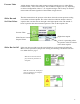
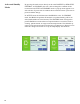
French Language Support on Default Screen & Data Entry Screen The home screen can be setup to show French Language words using the Setup Display Menu The following screens show the difference between English and French Home screens. Default screen for English version. Default screen for French version.
On the default screen the following changes will be made for the French version. PRESSURE PRESSION OPERATION OPĖRATION NEGATIVE NĖGATIVE NEUTRAL NEUTRE STANDBY ATTENTE DOOR PORTE WARNING ALERTE ALARM ALARME TEMPERATURE TĖMPERATURE SILENCE, NORMAL, HUMIDITY, RESET do not change When the language is selected as French in the setup display screen, French characters entry in the data screen will be enabled.
French Version—Letter A French Version—Letter E 38
French Version—Letter Y French Version—Letter Y 39
French Version—Letter I French Version—Letter O 40
French Version—Letter C French Version—Letter N 41
Troubleshooting Error/Trouble Condition Display shows: "Factory Calibration has been lost. Return to Factory for Calibration". Possible Cause Non-recoverable EEPROM checksum error of factory calibration data, ER01. Display shows: "Setup information Recoverable EEPROM checksum erhas been lost. Loading Default Values ror of unit setup configuration, ER02. Please Wait...". User cannot enter into menus because User has lost password. of password protection.
RETURNING PRODUCTS FOR REPAIR When returning a product to Setra Systems, the material should be carefully packaged and shipped prepaid to: Setra Systems, Inc. 159 Swanson Road Boxborough, MA 01719-1304 Attn: Repair Department To assure prompt handling, please refer to return instructions on our Web site at http://www.setra.com/tra/repairs/cal_rep.htm.