
Product specifications


©2014 Setra Systems, Inc. All rights reserved. The Setra Systems name and logo are registered trademarks of Setra Systems, Inc. Phone: 800-257-3872 • Fax: 978-264-0292 • setra.com
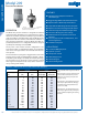
DIFFERENTIAL PRESSURE
73
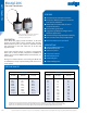
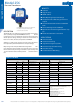
Model 206
Pressure Transducers
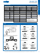
Cable
Current Output
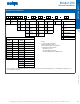
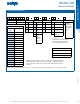
SPECIFICATIONS
Performance Data Environmental Data Electrical Data (Voltage)
Accuracy RSS
1
(at constant temp) ±0.13% FS
Operating
3
Temperature °F (°C) 32 to + 120 (0 to +50) Circuit 2-Wire
Non-Linearity, BFSL
±0.1% FS
Storage Temperature °F (°C) -20 to +160 (-30 to +70) Output
10
4 to 20 mA
11
25 psig Range
2
±0.2%
Operating Humidity 5 to 95% RH (non-condensing) External Load 0 to 800 ohms
Hysteresis 0.08% FS
Acceleration 10 g Maximum
5
Minimum Supply Voltage
(VDC)
9 + 0.02 x (Resistance of receiver plus line)
Non-Repeatability 0.02% FS
Shock
6
200g Operating Maximum Supply Voltage
(VDC)
30 + 0.004 x (Resistance of receiver
plus line)
Thermal Eects
Vibration
7
20g 50-2000 Hz
Electrical Data (Current)
Compensated Range °F (°C) -4 to +176 (-20 to +80)
Physical Description
Circuit 2-Wire
Zero Shift %FS/100°F (%FS/50°C) 1.0 (0.9)
Case Stainless Steel Output
10
4 to 20 mA
11
Span Shift %FS/100°F (%FS/50°C) 1.5 (1.4)
Pressure Fittings 1/4”NPT external G1/4A or M14 x 1.5 Optional External Load 0 to 800 ohms
Warm-up Shift 0.1% FS Total
Vent Through cable (Cable Version)
Via Zero Screw (Terminal Block)
Minimum Supply Voltage
(VDC)
9 + 0.02 x (Resistance of receiver plus line)
Response Time 5 Milliseconds
Electrical Connection 2 ft. Multiconductor Cable or 3 Screw Terminal Block Maximum Supply Voltage
(VDC)
30 + 0.004 x (Resistance of receiver
plus line)
Long Term Stability 0.5% FS/1 YR
Zero/Span Adjustments Top External Access
Electrical Data (Current)
1
RSS of Non-Linearity, Hysteresis, and Non-Repeatability.
2
25 psig range accuracy is ±0.22% of Full Scale output.
3
Hydrogen not recommended for use with 17-4 PH Stainless Steel.
4
The high temperature limit of the cable is 200°F (95°C).
5
Shift in output reading <0.05 psi/g typical; pressure port axis only.
6
Mil-Std. 202, Method 213B, Cond. C
Weight (approx.) 6 Ounces Circuit 3- Wire (Exc, Out, Com)
7
Mil-Std. 202, Method 204, Cond. C
8
Calibrated into a 50K ohm load, operable into a 5000 ohm load or greater.
9
Zero output factory set to within ±25mV. Span (Full Scale) output factory set to within ±50mV.
10
Calibrated at factory with a 24 VDC loop supply voltage and a 250 ohm load.
11
Zero output factory set to within ±0.08mA. Span (Full Scale) output factory set to within ±0.16mA.
Specications subject to change without notice.
Excitation 12 to 18 VDC, Rever Excitation Protected
Output
8
0.1 to 5.1 VDC
9
Output Impedence 100 ohms
Power Consumption <0.15 watts (approx. 5mA @ 24 VDC)
GAUGE PRESSURE