LSG60 Freeze Drier Title Customer SS Reference Fxxx Customer Reference N/A INSTALLATION AND OPERATION MANUAL 1HZ246 Issue 1 Date 26/10/05 Severn Science Ltd 8 Brunel Way Thornbury Bristol BS35 3UR Tel 01454 414723 Fax 01454 281680 Please Read This Document before Operating the Machinery
OPERATION MANUAL “customer” – LSG60 Freeze Drier – “contract ref” CONTENTS 1. DOCUMENTATION RECORDS 4 2. INTRODUCTION 5 2.1 Purpose 5 2.2 General safety 5 2.3 Unpack and inspect 5 2.4 Installation and Commission 2.4.1 Initial setup 2.4.2 Electrical requirements 2.4.3 Mechanical requirements 2.4.4 Lifting and Handling Instructions 2.4.4.1 General 2.4.4.2 Separation of the LSG60 2.4.4.3 Moving of the separate LSG60 units 2.4.4.4 Re assembling the units 2.4.
OPERATION MANUAL “customer” – LSG60 Freeze Drier – “contract ref” 4.8 5. 6. Trends 27 4.9 Setup 4.9.1 End Point Determination 4.9.2 Secondary Drying 4.9.3 Automatic Backfill 4.9.4 Automatic Stoppering 27 27 28 28 28 4.10 30 Manual Operation 4.11 Interlocks 4.11.1 Hardwired Interlocks 4.11.2 Software Interlocks 31 31 31 4.12 Alarms 4.12.1 Alarm Types 4.12.2 Alarm Display and Acknowledgement 31 31 31 4.13 Historical Logging 32 OPERATOR DISPLAYS 33 5.1 System Mimics 5.1.1 Home 5.1.2 Setup 5.
OPERATION MANUAL “customer” – LSG60 Freeze Drier – “contract ref” 1. DOCUMENTATION RECORDS Issue Documentation Update Details Date Approval 1a Project version 1a developed and issued for internal review 25/10/05 JH 1 First formal issue to customer. 26/10/05 JH 2 Section 3.2 + section 4.12.
OPERATION MANUAL “customer” – LSG60 Freeze Drier – “contract ref” 2. INTRODUCTION 2.1 Purpose This manual provides installation and operation instructions for the Freeze dryer. This manual and all accompanying documentation must be read before operating the vacuum system. Important safety information is highlighted as WARNING and CAUTION instructions; you must obey these instructions. The use of WARNINGS and CAUTIONS are defined below. 2.
OPERATION MANUAL “customer” – LSG60 Freeze Drier – “contract ref” 2.4 Installation and Commission 2.4.1 Initial setup I. Locate the freeze dryer in the required position, ensuring that the floor is adequate to support the equipment and that due consideration is given to: a) Air flow for ventilation (1metre min) b) Access to framework panels. (1metre min) c) Adequate space for maintenance. (1metre min) ! CAUTION: The ventilation holes in the framework panels must not be blocked or impeded in any way.
OPERATION MANUAL “customer” – LSG60 Freeze Drier – “contract ref” ! CAUTION: Check that the Gas Ballast control has not been left in the fully closed position (refer to manufacturer’s manual before operation). V. The cooling circuit in the drying unit uses a heat transfer fluid (silicone oil). Check the chamber insulation for signs of oil leaks and confirm that the oil reservoir is approximately half full (see figure 4). Severn Science Limited engineers to install and commission 2.4.
OPERATION MANUAL “customer” – LSG60 Freeze Drier – “contract ref” 2.4.4 Lifting and Handling Instructions 2.4.4.1 General The LSG60 Freeze dryer is designed to be moved as two separate units. The drying chamber assembly (left hand unit) and condenser assembly (right hand unit). The freeze dryer assembly should therefore be split into these 2 component parts prior to moving.
OPERATION MANUAL “customer” – LSG60 Freeze Drier – “contract ref” 9. Disconnect the four grey flexible braided water cooling hoses. 10.Now remove the six 8.0 x 100 socket head capscrews securing the two units together. Two are located in the top horizontal frame member. A further two in the middle horizontal frame member. The remaining pair are in the front and rear verticals, towards the base of the frame work. 11. Un bolt Drying chamber door interlock swith 12.
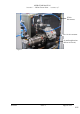
OPERATION MANUAL “customer” – LSG60 Freeze Drier – “contract ref” PT100 Disconnects Unic 10 valve actuator 22 mm Straight union (Silicon oil circuit) Figure 1 Section 2 Issue: 1 Page 10 of 42 XXX
OPERATION MANUAL “customer” – LSG60 Freeze Drier – “contract ref” Heat Exchanger water cooling hoses Figure 2 Silicon oil drain valve 2.4.5 Additional Documents to be supplied Electrical circuit diagrams Publication ref 8408 P&ID publication ref 8484 P&ID Key publication ref 1HY085 Alarm schedule Publication ref 1HY086. Interlock schedule Publication ref 1HY087.
OPERATION MANUAL “customer” – LSG60 Freeze Drier – “contract ref” 3. OVERVIEW 3.1 General Description The LSG60 Freeze Dryer is for the purpose of drying a wide range of approximately 150 aqueous products in a variety of different sizes of vials. Freeze drying is a method used to dehydrate materials via a process involving the sublimation of any water content (in the form of ice) under vacuum conditions.
OPERATION MANUAL “customer” – LSG60 Freeze Drier – “contract ref” Oil collected in the mist filter is continuously returned into the gas ballast port of the pump. The pump is operated on gas ballast to reduce the risk of water condensation in the pump oil (refer also to manufacturers instructions). The condenser temperature and pressure is monitored with a pirani gauge and a PT100 respectively; data can be continuously displayed on the touch screen if required.
OPERATION MANUAL “customer” – LSG60 Freeze Drier – “contract ref” user interface. Navigation between the User screens is achieved using standard display panes and function keys. User screen descriptions can be found later in this document. The 2500 modular process controller provides the Input/output interface for the control system, signal conditioning and PID control for the temperature. These two instruments talk to each other via a serial (RS422) communication link.
OPERATION MANUAL “customer” – LSG60 Freeze Drier – “contract ref” MENU KEY Figure 3 Section 3 Issue: 1 Page 15 of 42
OPERATION MANUAL “customer” – LSG60 Freeze Drier – “contract ref” Silicon oil reservior Drying chamber door Upper viewport Condenser Chamber Lower viewport Door swing clamps Drying chamber unit Condenser unit Location points for transit castors Figure 4 Section 3 Issue: 1 Page 16 of 42
OPERATION MANUAL “customer” – LSG60 Freeze Drier – “contract ref” 4. FUNCTIONS 4.1 Power up Power up is achieved via the control power switch located below the operator interface (see Figure 3) A power indicator illuminates to confirm that control system is on.
OPERATION MANUAL “customer” – LSG60 Freeze Drier – “contract ref” 2. Operator- User is able to download recipes run cycles, view alarm history, historical program trending, acknowledge alarms and edit user adjustable parameters. 3. Supervisor- As Operator but in addition can and edit recipes and customise the data logging facility. 4. Administrator- allows individual security accounts to be set up with access rights appropriate to each level of user.
OPERATION MANUAL “customer” – LSG60 Freeze Drier – “contract ref” ! CAUTION: The provided ‘stoppering jacks’ must be placed on all shelves prior to stoppering or damage to the shelves will result The freeze dryer can be used for both vial and bulk dying. The door to the dying chamber can be opened by first unscrewing the two swing clamps (see figure 4). With the swing clamps rotated clear the door can then be opened using the handle. Note: Do not use excessive force to open the chamber door.
OPERATION MANUAL “customer” – LSG60 Freeze Drier – “contract ref” Min -40 oC The user is able to load/download a recipe by the following operation i. Access to the Load/Save page = ‘MENU’ key / ‘RECIPE’ button ii. Touch ‘File name’ iii. Select required file from the pick list iv. Press enter v. To access the Recipe menu press the ‘LOAD’ button Press the ‘DOWNLOAD’ button The freeze drying cycle will start automatically. The recipe panel changes to blue.
OPERATION MANUAL “customer” – LSG60 Freeze Drier – “contract ref” • Press the file name field . A list of program names will appear in the left half of the screen. From the list, press the name of the program to be loaded. • Press the green RETURN key. The display returns to the Load /Save screen and the file name field now displays the name of the program that has been selected. • Press the LOAD button. At this stage, the selected program can either be run or modified from the Programmer screen.
OPERATION MANUAL “customer” – LSG60 Freeze Drier – “contract ref” • To run the program, press the RUN key. The Programmer screen will appear. The program panel changes to green indicting that the program is now running. The time when the program is due for completion is also displayed together with a number that indicates the number of segments that have been completed (see figure ).
OPERATION MANUAL “customer” – LSG60 Freeze Drier – “contract ref” c) From the Home screen, press the ‘Vent Valve’ icon. The icon changes from Red to Green. d) When the chamber reaches atmosphere, press the ‘Vent Valve’ icon again to close. The icon changes from Green to Red. If the chamber is automatically vented to atmospheric pressure at the end of the process (as per the program), no further action is required before removing the product.
OPERATION MANUAL “customer” – LSG60 Freeze Drier – “contract ref” EPD retest [hrs] SEC DRY select SEC DRY temp [oC] End Point Determination duration between tests Secondary Drying selected Secondary Drying temperature SEC DRY time [hrs] Secondary Drying duration BACKFILL select BACKFILL press Automatic Backfill selected Automatic Backfill pressure setpoint STOPPER select FINISH temp [oC] Automatic Stoppering selected Cycle completion temperature Min 0.01 mbar/s Max 60 hrs Min 0.
OPERATION MANUAL “customer” – LSG60 Freeze Drier – “contract ref” describes the freeze drying conditions of either temperature or pressure (pressure is controlled by the high vacuum valve which is either open or closed). Individual cells (denoted SP cells) define the temperature or pressure set points for any particular segment. The top row of cells (referred as ‘segment headings’) define the duration and the function name (e.g., freezing, primary drying etc) of each segment.
OPERATION MANUAL “customer” – LSG60 Freeze Drier – “contract ref” Table 3: Function Descriptions and Coding Function Name Dwell Step Ramp Ramp@ Function Description Temperature set point is held for duration of segment Temperature ramps to temperature set point as fast as possible Temperature ramps to temperature set point at a constant rate over the duration of the segment Temperature ramps to temperature set point at specified ramp rate SP code D Set point fields None S Temperature R Temperature R
OPERATION MANUAL “customer” – LSG60 Freeze Drier – “contract ref” To save the updated program under the same file name after editing is complete, or to save the program as a new file name, follow the procedure below. To insert or delete segments prior to saving, see sections 5.2 and 5.3. a) From the program editor screen, press the MENU button on the printed keypad. From the menu options press the PROGRAMMER button. The Programmer screen will appear. b) Press the PROGRAMS button.
OPERATION MANUAL “customer” – LSG60 Freeze Drier – “contract ref” Select/unselect the automatic backfill option by pressing the appropriate field which will toggle between YES and NO. Note: this can also be used to abort this sequence at any stage. The rate and repeat test time set point values can be modified by pressing the appropriate field and entering the value on the numeric keypad. Note: these changes will be effective immediately, overwriting any previously downloaded recipe values. 4.9.
OPERATION MANUAL “customer” – LSG60 Freeze Drier – “contract ref” ! CAUTION: The provided ‘stoppering jacks’ must be placed on all shelves prior to stoppering or damage to the shelves will result Note: The stoppering facility cannot be operated however until the ‘RESET’ button is pressed. (see figure 3) Automatic stoppering, when used with stoppering jacks (see figure 5), is used to fully stopper semi stoppered vials by hydraulically closing the product shelves.
OPERATION MANUAL “customer” – LSG60 Freeze Drier – “contract ref” Stoppering Hydraulic flow control ‘Stoppering’ pressure switch ‘Home’ pressure switch Home Hydraulic flow control Figure 6 4.10 Manual Operation Security level: Supervisor Manual mode- user is able to control the system, by individually operating components from the mimic screen. Manual mode is accessible by pressing the Manual button (Supervisor level) on the Home screen. Controllable parameters are as follows: 1.
OPERATION MANUAL “customer” – LSG60 Freeze Drier – “contract ref” 14. Shelf temperature Auto/Man control 15. Shelf temperature control output 4.11 Interlocks 4.11.1 Hardwired Interlocks For a complete list of interlocks refer to “Interlock schedule” Publication ref 1HY087. 4.11.2 Software Interlocks For a complete list of interlocks refer to “Interlock schedule” Publication ref 1HY087. 4.12 Alarms 4.12.1 Alarm Types Alarm severities are listed in “Alarm schedule” Publication ref 1HY086.
OPERATION MANUAL “customer” – LSG60 Freeze Drier – “contract ref” 4.13 Historical Logging Data can be logged to the 16MB internal memory during the freeze drying cycle. Data is recorded as a text file (.ASC) and can be later imported into most spreadsheet applications. The Archive interval is user adjustable (max rate 5secs). Log files can be given an 8character file name (using MS-DOS constraints). The data logged to disk is: 1. Active alarms 2. Shelf Temp PV 3. Shelf Temp SP 4. Shelf Press PV 5.
OPERATION MANUAL “customer” – LSG60 Freeze Drier – “contract ref” ‘Export’ causes the currently displayed file to be copied to the floppy disk or USB device, as selected. ‘Export All’ causes all files in the internal archive to be copied to the floppy disk or USB device. If the device becomes full during archive a message appears asking the user to fit a new disk. 5. OPERATOR DISPLAYS 5.1 System Mimics 5.1.
OPERATION MANUAL “customer” – LSG60 Freeze Drier – “contract ref” 5.1.
OPERATION MANUAL “customer” – LSG60 Freeze Drier – “contract ref” 5.1.
OPERATION MANUAL “customer” – LSG60 Freeze Drier – “contract ref” 5.
OPERATION MANUAL “customer” – LSG60 Freeze Drier – “contract ref” 6. MAINTENANCE ! WARNING: There is no safety interlock fitted to the electrical cabinet door. Ensure that the electrical supply is isolated before starting any maintenance work. 6.1 Planned Maintenance When performing the following operations, refer to the components own working instructions for details on how to carry out the specified items; all of the necessary working instructions are supplied with this manual. 6.1.
OPERATION MANUAL “customer” – LSG60 Freeze Drier – “contract ref” 6.2 Recommended Spares 6.2.1 General Table 4: Recommended Spare Parts List Description AXIAL VALVE SERVICE KITS CHAMBER DOOR SEAL. Part No 4243 00 10 30 X 1 (3/8”) 4243 00 15 30 X 1 (1/2”) Ø10.0 silicon ‘O’ ring chord x 4 metres. Ø305 i/d x 5.0 sect silicon ‘O’ ring. CONDENSER ACRYLIC VIEWPORT SEAL. SILICON OIL CIRCULATION HB527.0003 Huber Unipump ll, 2 PUMP stage. SILICON OIL. LS-1-013 (5ltr) VACUUM PUMP OIL H110 25 015.
OPERATION MANUAL “customer” – LSG60 Freeze Drier – “contract ref” 240V 400W, 1/4" COLD AT DISC END, 1/2" COLD AT LEAD END, 39" TEFLON LEAD AND SEAL. SVDA-3V25-AO2 SOLID STATE RELAY 25A Eurotherm 6.3 Edwards vacuum pump For the Edwards Vacuum pump refer to the individual manufacturers literature for spares. 6.4 Manufacturers literature Manufacturers literature for all major components have been included. 6.5 Self Diagnostic Facilities Both T800 and 2500 perform their own self check routines on start-up.
OPERATION MANUAL “customer” – LSG60 Freeze Drier – “contract ref” Table 5: Technical Specifications FUNCTION MODEL o Minimum condenser temperature (@ 25 C LSG60 ambient) Minimum shelf temperature (@ 25oC LS40 ambient) LS60 Shelf cool down times (with both LSG60 (to -35oC) refrigeration units and with no load, o (to –40oC) from 23 C ) (to –55oC) (to –60oC) Maximum shelf temperature LSG60 Temperature uniformity (between shelves LSG60 (to 0oC) measured at the inlet) (to –20oC) (to –40oC) (to –60oC) Temperature
OPERATION MANUAL “customer” – LSG60 Freeze Drier – “contract ref” • • • • • Temperature Operation 0 to + 30°C Temperature Storage -10 to +70°C Humidity Operation 50 to 85% RH (non condensing) Humidity Storage 5 to 95% RH (non-condensing) Protection IP22 (Electrical panel and front panel IP54) 9.
OPERATION MANUAL “customer” – LSG60 Freeze Drier – “contract ref” PID 2500 FLASH memory RTD T800 BMS RS232 PPE EPS EPD Section 10 Proportional / Integral / Derivative Eurotherm 2500 Input / Output unit A memory chip that can be rewritten and hold its content without power Resistance Temperature Detector Eurotherm T800 Visual Supervisor unit Building Management system Serial communications port Personal Protective Equipment End of Program Sequence End Point Determination Issue: 1 Page 42 of 42