
Specifications


OPERATION MANUAL
“customer” – LSG60 Freeze Drier – “contract ref”
2.4.4 Lifting and Handling Instructions
2.4.4.1 General
The LSG60 Freeze dryer is designed to be moved as two separate units. The drying
chamber assembly (left hand unit) and condenser assembly (right hand unit).
The freeze dryer assembly should therefore be split into these 2 component parts prior
to moving. The silicon oil reservoir fitted at the top and left hand side of the drying
chamber assembly, must be removed if moving this unit through areas with a height
restriction of less than 2110mm.
2.4.4.2 Separation of the LSG60
The LSG60 should be at ambient temperature with the condenser chamber fully drained.
The vacuum valve must be fully closed and the shelves in the fully lowered position
before commencing separation of the two units.
Ensure that power and all other services are safely and
fully disconnected from the
LSG60 assembly.
The four jacking feet on each unit should all be in full contact with the ground.
2.4.4.2.1 Draining the Silicon oil fluid circuit
The most efficient means of draining the Silicon oil fluid circuit is by the use of a
vacuum pump and catchpot assembly.
The Silicon oil drain valve is located at the rear and bottom of the drying chamber
unit. The valve can be identified by its yellow handle.
Connect the vacuum pump and catchpot assembly at this point. By opening the valve
the Silicon oil can now be evacuated from the system.
Remove aluminium covers from top of each unit. If required, the Silicon oil reservoir
may now be carefully disconnected and removed.
All services that are connected between the condenser unit and the drying chamber
unit can now be disconnected:-
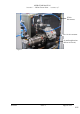
1. Unplug all of the (brown) Thermocouple cables from the top rear of the drying
chamber unit (see figure 1).
2. Disconnect the three pneumatic lines form the pneumatic control valves. And
disconnect / unplug the control valve electrical leads.
3. Disconnect the Nitrogen supplies to the control valves.
4. Unplug the two electrical connections to the Unic 10 valve actuator.
5. Immediately beneath the Unic 10 actuator head is an insulated Ø22mm copper
pipe. Remove the short piece of large diameter insulation and disconnect the Straight
union found beneath. A second Ø22mm copper pipe under the above item should
also be disconnected.
6. Remove the four clamps securing the ISO160 flexible metal pipeline to the Unic
10 valve body.
7. Disconnect the two Harting plugs. One to the side of the drying chamber and a
larger one to the rear.
8. Disconnect the Earth link.
Section 2 Issue: 1 Page 8 of 42