
Users Manual

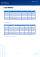
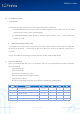
Table Of Contents

SGW101X Series
@2019 | SG Wireless Limited
Confidential Proprietary
Website : www.sgwireless.com
6
5. Module Interface
A. Power Management
i. Module supply input (VCC & VCCH)
The SGW101X series use integrated two step-down regulators (REG0 & REG1) to transform the supply voltage presented
at the VCC & VCCH pins into a stable system voltage. Each regulator can be programmed as Low-dropout regulator
(LDO) or Buck regulator (DC/DC), depends on the operating mode of the module. There are two operating modes for
the module which depends on the VCC and VCCH configuration:
o
Normal/Low Voltage (LV) mode
o High Voltage (HV) mode
Mode
Pin No
Pin Name
Connection
Normal
17
VCC
1.7 V to 3.6 V supply source input
65
VCCH
Same as VCC
High Voltage
17
VCC
1.8 V to 3.3 V output voltage for module internal operating supply
65
VCCH
2.5 V to 5.5 V supply source input
REMARK: In LV or HV mode, the GPIO logic level is determined by the VCC pin.
Table 5 Power Mode Pin connections
ii. USB Power input (VBUS)
The USB interface of the SGW101X series can be used in either Normal (LV) or High voltage mode of the module. The
inside USB peripheral has a dedicated internal voltage regulator for converting the VBUS supply to 3.3 V.